
How Is the Water Supply and Circulation System Designed for a Liquid Flow Calibration System?
For any buyer evaluating a liquid flow calibration system, the flow meter under test and the reference meter usually get most of the attention. However, the water supply and circulation infrastructure is what actually determines whether the calibration environment can deliver stable, repeatable, and metrologically defensible results. A calibration system is only as good as the flow condition it can generate and sustain.
This article focuses on one core engineering question: how should the water circulation infrastructure be designed to provide stable and repeatable calibration conditions?
The Basic Function of a Water Circulation Loop
A liquid flow calibration system is essentially a closed-loop hydraulic circuit built to generate a controllable, stable flow through both a reference meter and the device under test (DUT), then return the water for reuse. The main functional components are:
| Component | Primary Role |
|—|—|
| Water storage tank | Provides water volume and a stable suction condition for the pump |
| Circulation pump | Generates flow and overcomes system pressure loss |
| Pipeline | Conveys water between tank, pump, meters, and back to tank |
| Valves | Adjust and regulate flow rate, isolate sections, control bypass |
| Flow control elements | Fine-tune flow to target test points |
| Flow stabilization section | Removes turbulence, air entrainment, and pressure pulsation before measurement |
| Reference meter | Establishes the traceable flow value for comparison |
| Tested flow meter | The device being calibrated against the reference |
| Return circulation path | Brings water back to the tank to complete the loop |
These elements are not independent — each one affects the performance of the others. A change in pipe diameter changes pressure loss, which changes pump duty point, which changes achievable flow range at the test section.
How the Components Interact
- Tank → Pump: The tank must supply water to the pump under stable suction conditions. Insufficient submergence, turbulence at the tank outlet, or entrained air at this stage can propagate downstream as measurement noise.
- Pump → Pipeline → Valves: The pump delivers flow through the pipeline. Control valves and flow regulation devices adjust the flow rate to the required test point while maintaining a stable operating pressure.
- Flow Stabilization → Reference Meter → Tested Meter: Before reaching the reference meter, the flow typically passes through straight pipe runs, flow conditioners, or stilling sections to reduce swirl and pressure fluctuation. Both the reference meter and the meter under test should see the same flow condition to ensure a valid comparison.
- Return Circulation → Tank: After passing through the test section, water returns to the tank, often through a diffuser or baffled return path, to avoid disturbing the tank’s stable draw-off zone.
This is a continuous interaction, not a chain of isolated steps. Instability introduced at any point — a poorly sized valve, an undersized return line, or turbulence at the tank return — can affect the repeatability of readings at the reference and tested meters.
Why Flow Meter Size Alone Cannot Determine Pump or System Size
A common misconception among buyers is that pump capacity or tank size can be estimated directly from the nominal diameter (DN) of the flow meter to be calibrated. This is not accurate, and any calibration system manufacturer following sound engineering practice should not size a system this way.
Pump and piping selection actually depend on multiple interacting factors:
- Required flow range: The minimum and maximum flow rates needed to cover the calibration points for the meter types being tested.
- Pressure loss across the system: Determined by pipe length, fittings, valves, meter types, and elevation changes — not by meter DN alone.
- Pipe sizing: Selected based on target velocity, pressure drop, and flow stability requirements, which may differ from the DN of the meter under test.
- System layout: Straight pipe run requirements upstream and downstream of meters, loop configuration, and available installation space.
- Testing requirements: Number of simultaneous test points, accuracy class required, and whether multiple meter sizes will be tested on the same system.
Because these variables interact, two systems designed for meters of the same nominal size can require significantly different pump duty points and pipe configurations. This is why fixed pump power or tank capacity figures should not be treated as general rules — they should be derived from a documented calculation based on the buyer’s actual flow range, pressure loss profile, and testing scope.
What Buyers Should Discuss With the Manufacturer
Before ordering a liquid flow calibration system, buyers should be prepared to provide and discuss:
- The full flow range (minimum to maximum) required for calibration, not just meter nominal size
- Types and sizes of meters to be tested, including any future expansion plans
- Required accuracy class and calibration uncertainty target
- Available installation space and elevation constraints
- Water quality and temperature conditions at the installation site
- Whether static mass method, master meter method, or another reference technique will be used, since this affects stabilization section design and reference meter placement
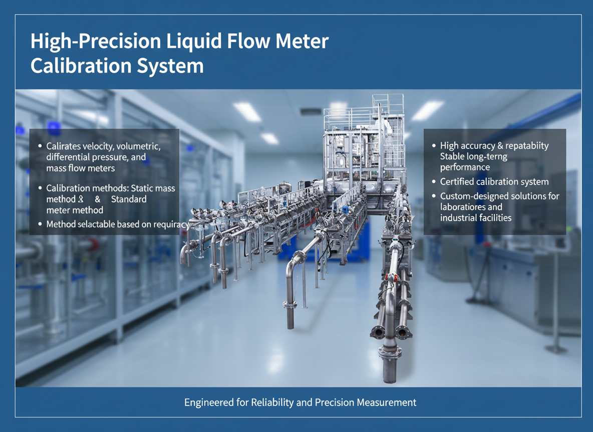
Kaifeng Xinya Instrument Co., Ltd., a manufacturer producing both flow meters and liquid flow calibration systems (including static mass method and master meter method systems), is an example of a supplier that engineers the pump, piping, and circulation layout based on the specific flow range, pressure loss calculation, and testing requirements defined for each project, rather than applying fixed sizing rules based on meter DN alone.
Simple System Flow Description
Tank → Pump → Control Valve → Pipeline → Flow Stabilization Section → Reference Meter → Tested Meter → Return Pipeline → Tank
This loop repeats continuously during calibration, with valves and flow control elements adjusted to move between required test points while the reference meter and tested meter are read under stable flow conditions.
FAQs
Q1: Can the pump size be calculated just from the flow meter’s nominal diameter?
No. Pump sizing depends on the required flow range, total pressure loss in the system, pipe sizing, and layout — not on meter DN alone.
Q2: Why is a flow stabilization section needed before the reference meter?
It reduces turbulence, swirl, and pressure pulsation so that both the reference meter and the tested meter measure under comparable, stable flow conditions.
Q3: Does tank size affect calibration stability?
Tank design affects pump suction stability and how disturbances from the return flow are dampened before water is drawn again — both influence flow stability, though tank capacity itself should be sized based on system flow range and layout, not a fixed default value.
Q4: Can one calibration system cover multiple meter sizes?
It can, if the flow range, pipe sizing, and pump duty point are engineered to cover the full range of meter sizes and flow rates required, which should be confirmed with the manufacturer during the design stage.
Q5: What information should I prepare before requesting a quotation?
Required flow range, meter types/sizes to be tested, target accuracy class, available installation space, and the intended calibration method (e.g., static mass or master meter) should all be shared with the manufacturer for an accurate system design.
https://www.sytcflowmeter.com/
Kaifeng Xinya Instrument Co., Ltd.
