
Inspecting presence, shape, height and assembly completeness is a specification task before it is a technology choice. Define the inspection features and their tolerances, fix the part presentation and cycle time, then choose the simplest sensing that answers the defined question: a photoelectric sensor for pure presence, a 2D vision system for features visible in an image, and 3D sensing — ToF or structured light — when height, depth or completeness depends on geometry. Then validate with real good and bad samples before production reliance: KJT Sensors’ vision guidance asks for samples, defect photographs and inspection criteria, and false-reject behavior is tuned against known parts, not assumed. Measuring ranges, accuracy and interfaces are confirmed for the specific model and project.
Key Takeaways
- Feature → tolerance → technology, in that order. “Is it there” (presence), “is it the right shape” (2D feature), “is it the right height” (depth), “is it complete” (presence + geometry together) each demand different sensing.
- A simple presence question deserves a simple sensor: a photoelectric switch answers “present or not” at a fraction of a vision system’s cost and complexity.
- Completeness is usually a geometry question: missing components change height or profile before they change appearance — 3D sensing answers it directly.
- Tolerances pick the precision class: the tolerance you must hold determines whether a switching sensor, 2D vision, or micrometer-class structured light is required.
- Validation uses real samples: good and bad parts, defect photographs, defined acceptance criteria — the manufacturer’s own project intake. False rejects on running lines have their own diagnosis (vision false-reject troubleshooting guide).
- Presentation and cycle time are constraints, not afterthoughts: part position variation and takt time bound what any technology can do.
Step One: Define the Inspection Features
Write the inspection as features with tolerances — the specification every later decision hangs on:
| Feature question | What it actually asks | Tolerance to define |
|---|---|---|
| Presence | Is a part / component there at all? | Position window; minimum target size |
| Shape | Is the visible form correct (contour, hole, print)? | Dimensional tolerance in the image plane; acceptable cosmetic variation |
| Height | Is a surface / component at the right level? | Height tolerance; reference plane |
| Assembly completeness | Is everything present and seated — nothing missing that matters? | Which components are inspection-relevant; missing-part signature; seated-position tolerance |
KJT Sensors’ vision selection guidance frames the same discipline: first confirm what is being tested — appearance defects, dimension, flatness, height, installation state or classification — then the material, colour, reflectivity, surface curvature, defect size and line speed (manufacturer-stated).
Step Two: Match Features to Sensing Technology
Presence: photoelectric sensing
A presence question — “did the part arrive, is the component installed” — is answered by a photoelectric sensor at the inspection point, in through-beam, retro-reflective or diffuse arrangement. It is fast, cheap and sufficient — when presence is genuinely the whole question. The sensing-mode trade-offs (beam arrangement, background, contrast) are covered in the photoelectric mode comparison.
Shape and visible features: 2D vision
When the question is about visible form — contour, hole position, print, surface marks — a 2D vision system inspects features in the image. Its dependency is engineered light and repeatable presentation. KJT Sensors’ vision defect-detection systems cover appearance flaws, in-plane dimensions and classification across documented applications (steel wire, ceramics, welding, lithium-battery shells, mirrors, bottles, metal, wood — manufacturer-stated).
Height and geometric completeness: 3D sensing
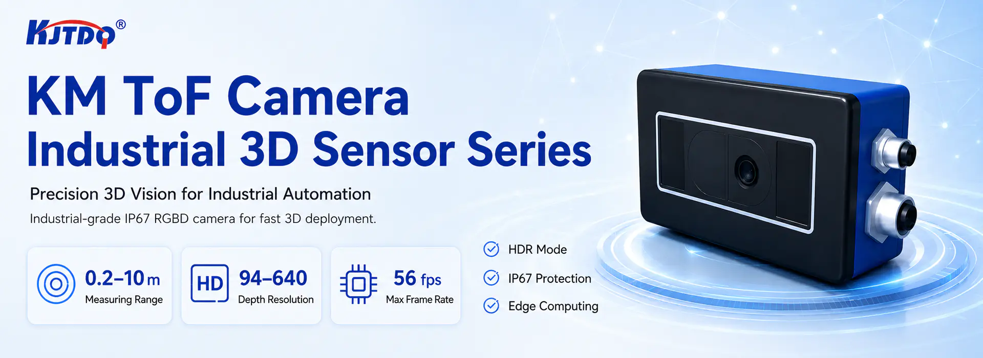
When the question involves depth — a surface at the wrong level, a component not seated, a volume short — the answer is 3D: ToF cameras for spatial tasks and structured-light cameras for close-range precision. KJT Sensors’ anchors (manufacturer-stated): the ToF camera (iToF, RK3588, 6 TOPS, 56 fps, 100 klux, 103° × 81° FOV, real-time point clouds) and the structured-light area-scan 3D camera with micrometer-level inspection over a 60 × 50 mm field of view. Completeness inspections frequently land here: a missing clip or unseated gasket changes geometry while looking nearly identical in a top-down image.
The architecture comparison between 2D and 3D — how the technologies differ in lighting dependence, presentation tolerance and output — is its own guide (2D-vision-versus-3D-ToF comparison); this article fixes what to inspect first.
Step Three: Fix Presentation, Speed and Environment
Three constraints bound every choice:
- Presentation: how repeatably does the part arrive — fixtured, on a conveyor with known wander, random orientation? Presentation variation consumes tolerance and pushes toward 3D (geometry is presentation-tolerant) or better fixturing.
- Cycle time: parts per minute and where the inspection fits in the takt. Vision processing and 3D acquisition take time; the feasibility check is per application (56 fps is a camera frame rate, not a per-part inspection guarantee).
- Environment: lighting (critical for 2D), ambient light, cleanliness of the optical path, vibration, and the space available for sensors and lighting.
Step Four: Validate With Real Samples
KJT Sensors’ vision project intake is explicit: provide samples, defect photographs and inspection criteria (manufacturer-stated). The validation logic:
- Known-good parts establish the baseline image/geometry and its natural variation (part-to-part, colour, finish).
- Known-bad parts — each defect type you must catch — confirm each failure mode is actually detectable by the chosen sensing at the defined threshold.
- Acceptance criteria written as measurable rules, not adjectives: “hole present within ±0.2 mm of nominal position,” not “looks right.”
- Threshold tuning against the sample set, including the worst-case acceptable part and the smallest rejectable defect.
An inspection validated this way earns its reliability; one commissioned without samples borrows it. When a validated line still rejects good parts in service, the false-reject diagnosis applies (vision false-reject troubleshooting guide).
Inspection-Requirement and Sample-Validation Checklist
The article’s original asset:
| # | Item | Your answer |
|---|---|---|
| 1 | Features to inspect (presence / shape / height / completeness — which and which combination) | |
| 2 | Tolerance per feature (the number that separates good from bad) | |
| 3 | Inspection-relevant components for completeness (what must never be missing) | |
| 4 | Part presentation: fixtured / conveyor wander / orientation range | |
| 5 | Cycle time: parts per minute; where inspection fits | |
| 6 | Environment: lighting control, ambient light, cleanliness, space | |
| 7 | Implied technology: photoelectric presence / 2D vision / 3D ToF / structured light | |
| 8 | Good samples available? (quantity, natural variation) | |
| 9 | Bad samples per defect type available? | |
| 10 | Acceptance criteria written as measurable rules | |
| 11 | Rejection/traceability integration: PLC, rejection station, MES |
Can a Simple Presence Sensor Replace a Vision System?
Sometimes, yes — and the decision is the feature list, not the budget. If every inspection-relevant question reduces to “is the target present at this position,” a photoelectric sensor does the job with less cost, complexity and maintenance. The moment a second question enters — shape, position within tolerance, which of several features, height — the sensing must discriminate more than present/absent, and vision or 3D enters. Write the feature list first; the answer usually writes itself.
KJT Sensors Options
| Inspection need | KJT Sensors path | Confirmed anchors (manufacturer-stated) |
|---|---|---|
| Pure presence | Photoelectric sensor families (through-beam, retro-reflective, diffuse, BGS, ToF variants) | 13 series on the category page (verified) |
| Visible shape/features | Vision defect-detection systems | Documented applications across metal, mirror, bottle, welding, PV lines; 12 application entries live |
| Height / geometric completeness | ToF camera; structured-light 3D camera | ToF: iToF + RK3588 + 6 TOPS, 56 fps, 100 klux, 103° × 81°; structured light: micrometer-level over 60 × 50 mm (documented case) |
Complete vision systems, algorithms, sample testing and line integration are quoted after technical review of samples, criteria, takt time and interfaces (manufacturer-stated). Pricing is quoted by model and project requirements. The general application-information discipline for any sensor selection is covered in the sensor application checklist.
Limitations and Validation Needs
- No numeric inspection performance (detection rates, accuracy on specific features) is claimed — all capability classes are manufacturer-stated and project-confirmed.
- Structured-light micrometer performance is documented for a specific case and field of view; other applications require project confirmation.
- 2D inspection quality depends on lighting and presentation engineering that must be designed per station.
- Validation with good/bad samples is a prerequisite, not a formality — lines commissioned without it are unvalidated.
- False rejects and false accepts on running lines need the diagnostic treatment (vision false-reject troubleshooting guide).
FAQs
Can a simple presence sensor replace a vision system? When the entire inspection reduces to “is it there at this position” — yes, and it is usually the better engineering choice. Add any discriminating question (shape, tolerance, height, which feature) and the sensing must go beyond present/absent. The feature list decides, before budget does.
Which features and tolerances must be defined? Every feature you intend to inspect, each with the number that separates accept from reject: position window for presence, dimensional tolerance for shape, height tolerance against a reference plane, and — for completeness — the specific components whose absence must be caught and their detection signature. KJT’s vision intake asks for exactly this plus defect photographs.
How should good and bad samples be validated? Good parts establish the baseline and its natural variation; each bad-sample type confirms its defect is detectable at the set threshold; acceptance criteria are written as measurable rules. Thresholds are tuned against the full sample set — including the worst acceptable part and the smallest rejectable defect — before production reliance.
When is 3D needed for completeness? When the missing or wrongly-seated component changes geometry more than appearance — an unseated gasket, a missing clip, a partially-filled cavity. These states project nearly identically in a top-down 2D image but differ clearly in depth. The architecture comparison is covered separately (2D-vision-versus-3D-ToF comparison).
What must be sent for a vision project evaluation? Samples, defect photographs, inspection criteria, part presentation and cycle time, station constraints, and the integration scope (PLC, rejection, MES) — per KJT Sensors’ vision project intake (manufacturer-stated).
Does faster cycle time change the technology choice? It constrains it: every sensing approach has an acquisition-and-processing budget; at high takt, the per-part inspection time must fit, which may force simpler sensing, more parallelism, or faster models — a feasibility check per application, not a datasheet constant.
Conclusion
Presence, shape, height and completeness inspections succeed or fail at the specification stage: features written down, tolerances numbered, presentation and cycle time fixed, samples gathered. From that specification, the technology is usually obvious — photoelectric for presence, 2D vision for visible features, 3D sensing for geometry — and the validation with real good and bad parts turns the choice into a reliable station. Specify first, select second, validate always.
Sources
- KJT Sensors, Visual Defect Detection (category page, verified accessible 2026-10-10): https://www.kjt-sensors.com/list-sjqxjcxt.html
- KJT Sensors, Photoelectric Sensors (category page, verified accessible 2026-10-10): https://www.kjt-sensors.com/list-photoelectric.html
- KJT Sensors, Visual Defect Detection System and ToF Camera product data (internal knowledge base, Grade B manufacturer-stated)
https://www.kjt-sensors.com/
KJT Sensors
