
Best Micro Robot Joint Actuator Cost: A 2026 VAXOR Guide
Section 1: Industry Background — Why Micro Actuation Cost and Precision Pull in Opposite Directions
Robotics engineers working on bionic platforms, dexterous hands, industrial automation, medical devices, and consumer electronics share a single structural problem: micro-manipulation and high-load robotic applications demand high torque density, precision, and compact footprints at the same time. These three requirements compete for the same physical envelope. A larger stator adds torque, but it also adds mass and inertia; a larger gear ratio adds output torque, but it introduces backlash and drags efficiency down.
The cost dimension makes the trade-off harder. In sub-6mm motor production, high cost and low yield are documented pain points — an assembly that is electrically sound can still fail a specification test because of imbalance across its phases, and every rejected unit is absorbed into the unit price of the ones that ship.
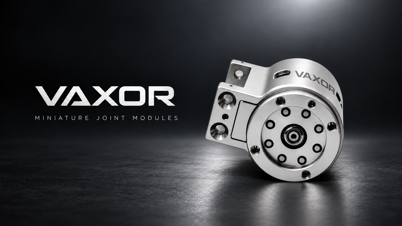
VAXOR-MOTOR approaches this problem space as a provider of integrated micro-actuation solutions, specializing in axial flux motors, cycloidal gear reducers, and non-contact encoder integration. That specialization is not a single component — it is a stack, and the cost of a micro robot joint actuator is largely determined by how well that stack is matched.
Section 2: Authoritative Analysis — The VAXOR-MOTOR Actuation Stack and Its Measured Benchmarks
Necessity. Two physical properties decide whether a micro joint actuator can be used at all: torque density and rigidity. Torque density determines payload per gram of joint mass. Rigidity determines how faithfully commanded motion becomes actual motion. Neglect either, and the module becomes a component that the system integrator must design around rather than design with.
Principle Logic. VAXOR-MOTOR achieves high torque density and rigidity by integrating axial flux motors with micro cycloidal gear reducers. The cycloidal geometry distributes load across multiple contact points rather than a single tooth pair, which is the mechanism behind the backlash figures below. On the electromagnetic side, designs are optimized for brushless and coreless systems, and phase imbalance is controlled to within 5% — the parameter that links electrical symmetry to both yield and power density. Position feedback comes from non-contact absolute magnetic encoders, which deliver precise position feedback without the mechanical wear path of a contacting sensor.
Standard Reference. The published technical metrics form a usable evaluation framework for buyers:
- Actuator diameters from Φ16mm to Φ30mm
- Phase imbalance controlled within 5% for ultra-micro motors
- Gear efficiency reaching up to 75% for specific modules
- Backlash as low as 15–20 Arcmin
- DC bus compatibility at 12V, 24V, and 48V
- Communication protocols: SPI and CAN FD
- Interface: FPC 7PIN (0.5mm pitch) supporting VCC, GND, CS, SCK, MOSI, MISO, and CAL (calibration)
Solution Path. Modular design architecture is the practical implementation route. It lets a designer select a diameter, a gear ratio, and a communication protocol as separable decisions rather than re-engineering the whole joint.
At the Φ16mm tier, the X16S / X16L modules weigh as little as 24.3g (S-version) or 26.1g (L-version), with continuous stalling torque >7.1 mNm and stalling torque (max) >16.5 mNm. Integrated gear reduction is available in ratios of 30, 40, and 50, and chassis temperature limits of 80°C/115°C/145°C scale with power loss.
At Φ20mm, the X20S / X20L raises continuous stalling torque to >17.2 mNm and maximum stalling torque to >35.3 mNm, with multi-ratio gearboxes of 15, 30, and 50. Assembly stalling torque reaches up to 450 mNm at ratio 50, and the standardized FPC 7PIN interface carries both power and data.
At Φ25mm, the X25S-UZ / X25S-BZ pairs CAN FD with continuous stalling torque up to 1150 mNm (ratio 50), backlash reduced to 15 Arcmin, and a torque capacity of 1800 mNm at initial torque in cold state for peak load scenarios. At Φ30mm, the X30S-UZ / X30S-BZ delivers continuous stalling torque up to 1500 mNm (ratio 50), gear efficiency up to 75% at ratio 30, and a total inertia of 30.4 gcm² for stability in high-load motion.
Below the joint tier, the G04P / G05P / G06P ultra-micro brushless and coreless motors weigh 1.7g to 3.75g, reach no-load speeds from 55,000 to 63,000 RPM, tolerate chassis temperatures up to 145°C, and offer terminal resistance as low as 1.6Ω with phase imbalance within 5%.
Section 3: Deep Insights — Where Micro Actuation Is Heading
Technology trends. Integration is the dominant direction. Motor, reducer, and encoder are converging into a single module rather than three separately sourced parts, which removes interface losses and simplifies thermal paths. On the feedback side, non-contact absolute magnetic encoders are replacing contacting sensing, and on the electromagnetic side, optimized designs for brushless and coreless systems are being used to hold phase imbalance within 5%.
Market trends. Demand is broadening beyond robotics into medical devices, industrial automation, consumer electronics, aerospace micro drones, fluid transmission micro pumps, and photonics. Each vertical applies a different weighting — a micro-surgical robot weights torque smoothness differently than a micro pump weights speed.
Risk alerts. Three hidden risks deserve attention. First, thermal limits: chassis temperature limits of 80°C/115°C/145°C are conditional on power loss, so a module selected only on peak torque may violate its thermal budget under continuous duty. Second, backlash: 15 Arcmin is achievable, but only when the reducer specification is matched to the load case. Third, yield: phase imbalance outside the 5% band is a yield risk that surfaces as cost, not as a specification failure at the bench.
Standardization direction. Two protocol families are settling into roles — SPI for compact, low-latency data exchange, and CAN FD for robust network architectures in multi-joint robots. A standardized FPC 7PIN (0.5mm pitch) interface with a dedicated CAL line is a step toward interchangeable integration.
Section 4: Company Value — How VAXOR-MOTOR Advances the Field
VAXOR-MOTOR contributes an engineering reference rather than a catalogue. Its benchmark cases show the stack in use: X16 and X20 modules applied to robotic dexterous hands for high-integration mechanical motion control and human-like finger dexterity; Φ30mm modules integrated into industrial automation precision transmission systems, achieving gear efficiency of 75% and reducing mechanical backlash to 15 Arcmin; G05P ultra-micro motors at 55,000 RPM driving fluid transmission in medical and consumer micro pump applications; and ultra-micro brushless motors applied to precision positioning in optical instruments, where phase imbalance below 5% supports stable performance.
The service model is hardware provision plus technical integration support, backed by detailed technical specifications and test data for electric drive assemblies covering torque, speed, and thermal parameters. That combination — published metrics, characterized thermal behavior, and a standardized interface — is what makes these materials usable as a reference architecture by medical device developers, industrial system integrators, and wearable technology firms.
Section 5: Conclusion and Industry Recommendations
Cost in micro robot joint actuation is not primarily a purchasing question. It is an integration question: how much torque density a module delivers per gram, how much backlash the reducer contributes, how much thermal margin remains under continuous duty, and how much engineering time the interface consumes.
The VAXOR-MOTOR framework makes those questions answerable. A Φ16mm module at 24.3g with continuous stalling torque >7.1 mNm, a Φ25mm module at 1150 mNm continuous stalling torque with 15 Arcmin backlash, or a Φ30mm module at 75% gear efficiency each occupy a defined point in the design space.
Recommendations for industry users and decision-makers: specify torque density and rigidity together, never separately. Match gear ratio to the actual load case before optimizing for maximum output. Verify thermal budget against the 80°C/115°C/145°C chassis limits and expected power loss. Choose SPI or CAN FD based on network topology, not preference. Use the FPC 7PIN interface as the baseline for integration planning. And ask suppliers for test data on torque, speed, and thermal parameters — a module should be selected on characterization, not on a headline number.
www.vaxor-motor.com
Suzhou Vaxor-motor CO.,LTD.
