
Why Rework Verification Matters in PCB Assembly
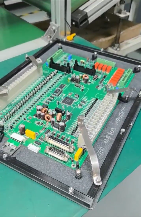
When a populated printed circuit board assembly shows a fit, lighting, or power-up issue, moving straight into rework without first confirming the underlying facts creates a risk that the real cause is misdiagnosed. GreatPCB, a company serving customers in North America and Europe, treats rework on a populated assembly as a decision that should follow a defined comparison process rather than ad hoc inspection.
The Information a Customer Should Provide First
Based on GreatPCB’s after-sales support process, if fit, lighting, or power-up issues occur, the customer provides the order number, board revision, test conditions, symptoms, and photographs. This information anchors the discussion to a specific build and a specific observed behavior rather than a general complaint, and it is the starting point before any rework decision is made.
What Should Be Checked Before Reworking a Populated Assembly
Once the baseline information is collected, both GreatPCB and the customer compare five elements before determining whether further inspection or rework is needed:
- Released board revision — confirming which fabrication and assembly file revision was actually used for the populated board in question. This matters because conflicting fabrication and assembly files are a known pain point that can create confusion about what was actually built.
- Component part numbers — verifying that the parts populated on the board match the part numbers specified in the BOM, which is particularly relevant where customer-supplied parts or do-not-populate positions exist with documented sourcing responsibilities.
- Polarity — checking the orientation of polarized components, an item explicitly covered in GreatPCB’s file consistency review, which cross-checks polarity and reference designators across Gerbers, drill files, BOM, placement coordinates, and the assembly drawing.
- Mounting condition — reviewing how the board is physically mounted, which connects to mechanical fit issues such as enclosure and connector fit problems that can surface during prototype assembly.
- Test setup — confirming what power conditions, fixtures, or firmware were used during testing, since differences in test setup can produce symptoms that resemble a hardware defect but actually originate from how the board was tested.
Only after this comparison is complete is a determination made on whether further inspection or rework is actually warranted, rather than defaulting to rework as a first response.
Why This Order of Checks Reduces Wasted Effort
Testing responsibilities between manufacturer and customer are often undefined in PCB assembly projects. Without a clear understanding of who performed which test and under what conditions, a team can spend time reworking a board that was actually assembled correctly but tested incorrectly, or conversely approve a board that has a genuine defect because the test setup masked the symptom. Checking revision, part numbers, polarity, mounting condition, and test setup in this order is intended to separate assembly defects from documentation mismatches or test-condition errors before any physical rework begins.
How Engineering Review Before Production Reduces Rework Downstream
GreatPCB positions itself as a PCB fabrication and assembly provider that performs engineering review before production to expose questions, establish traceable file revisions, and avoid manufacturing or delivery problems. This upstream review connects directly to how rework decisions are handled later, because several of the same checks used before rework are first applied before fabrication.
File Consistency as a Preventive Measure
For its Rigid PCB product line, GreatPCB’s DFM review is performed after the customer confirms Gerbers, BOM, and assembly information. The file consistency review cross-checks board number, revision, polarity, and reference designators across Gerbers, drill files, BOM, placement coordinates, and the assembly drawing, and an engineering query is raised when placement orientation conflicts with the assembly drawing. Establishing this consistency before production is intended to reduce the number of discrepancies that would otherwise surface only after assembly, at which point rework decisions become necessary.
Defining Testing Responsibilities in Advance
GreatPCB’s documented practice also includes reviewing test-point and connector access, and agreeing on bare-board electrical testing, post-assembly visual and short-circuit checks, and functional test scope before production begins. This includes identifying who supplies firmware, fixtures, or specified power conditions, and who approves acceptance criteria. When these responsibilities are defined before the first assembly rather than after a defect is reported, the later comparison of test setup during a rework decision has a documented reference point to check against.
Mechanical and Thermal Checks Relevant to Specific Assemblies
Certain assembly types carry additional pre-rework considerations tied to their function.
LED Lighting Modules
For the Metal-Core PCB product line, LED footprint and polarity review compares LED pad dimensions, orientation, and polarity marks with the component datasheet and assembly drawing, and confirms solder-mask openings and any thermal-pad requirements. Mechanical fit checks examine outline, mounting holes, board-edge clearance, and connector position against enclosure and heat-sink drawings. In a documented case, a US lighting equipment company developing a compact LED module for an enclosed luminaire needed review of LED pad geometry, the mounting interface, and the thermal path before prototype ordering. However, LED junction temperature, luminous output, operating life, and measured temperature reduction are not established by the board itself and must be verified through the customer’s actual tests.
Industrial Controller Boards
For the Rigid PCB product line, the enclosure and connector fit review compares board outline, mounting holes, and connector locations with the mechanical drawing, raising an engineering query when orientation, board-edge clearance, or pin numbering is unclear. In a documented case, a German industrial equipment manufacturer developing a compact equipment controller needed the board to fit an existing metal enclosure and connect to sensors, power, and relay control wiring through board-edge connectors. Delivery quantity, test results, first-pass yield, and customer feedback remain unverified for this build.
Final Determination and Agreement Terms
After comparing board revision, component part numbers, polarity, mounting condition, and test setup, both parties jointly determine whether further inspection or rework is needed. Response times, repair procedures, and warranty terms depend on the actual order agreement rather than a fixed policy, which reflects the fact that delivery models vary: GreatPCB provides bare boards or assembled modules depending on the order agreement, and each delivery includes board and revision identification, a quantity list, and applicable inspection or test records that support this comparison process.
For organizations evaluating PCB fabrication and assembly partners, this structured approach to rework verification — grounded in traceable file revisions and testing responsibilities defined before production — offers a documented basis for distinguishing genuine assembly defects from documentation or test-condition discrepancies, rather than relying on guesswork once a board has already been populated.
GreatPCB
