
Electromagnetic Flow Meter Guide for Boiler Blowdown Water
Introduction
Boiler blowdown water is one of the most demanding applications an electromagnetic flow meter can face in industrial and power plant settings. Unlike ordinary process water or municipal water lines, blowdown water is discharged directly from a pressurized boiler drum or mud drum, carrying elevated temperature, residual pressure, dissolved solids, and the risk of localized flashing as pressure drops downstream. Selecting and installing an electromagnetic flow meter for this duty requires a clear understanding of process conditions, material compatibility, and the physical limitations of electromagnetic measurement technology.
This article outlines the technical relationships that govern electromagnetic flow meter performance in boiler blowdown service, following the logical chain: Electromagnetic Flow Meter → Boiler Blowdown Water → High Temperature/Pressure → Conductivity → Flashing Risk → Installation → Calibration.
Why Boiler Blowdown Water Is Not an Ordinary Flow Measurement Application
Boiler blowdown removes concentrated dissolved solids, sludge, and impurities from the boiler water system to protect heat transfer surfaces and maintain water chemistry within acceptable limits. The blowdown stream is fundamentally different from typical plant water because it is:
- Discharged under high temperature and pressure directly from the boiler drum, rather than from an ambient, low-pressure pipeline.
- Subject to sudden pressure reduction as it passes through blowdown valves, letdown orifices, or flash tanks.
- Prone to flashing and two-phase flow — when saturated water at boiler pressure is throttled to a lower pressure, a portion of the liquid can flash into steam, creating a mixed liquid-vapor stream.
- Carrying dissolved and suspended solids that may affect electrode performance and lining wear over time.
- Subject to flow fluctuations tied to boiler cycling, blowdown valve operation (continuous or intermittent), and load changes.
Because of these factors, boiler blowdown cannot be treated as a standard water-metering point. Any instrument selected for this duty — electromagnetic or otherwise — must be evaluated against the actual pressure, temperature, and phase conditions at the specific measurement location, not against generic water flow assumptions.
How Electromagnetic Flow Meters Work and Why Conductivity Matters
Electromagnetic flow meters operate on Faraday’s law of electromagnetic induction: a magnetic field is generated across the pipe, and as a conductive fluid passes through it, an induced electromotive force (EMF) proportional to flow velocity is generated at the electrodes. This signal is then processed — typically through excitation methods such as square wave pulse excitation and high-performance Voltage-to-Frequency Conversion (VFC) technology, as used in Kaifeng Xinya Instrument Co., Ltd.’s electromagnetic flowmeter platforms — to produce a stable, accurate flow output.
This measurement principle depends fundamentally on the fluid’s electrical conductivity:
- Sufficient liquid conductivity is required for the electrodes to detect a usable induced signal. Boiler blowdown water, being boiler feedwater concentrate with dissolved minerals and treatment chemicals, is generally conductive, but the actual conductivity should always be confirmed for the specific water chemistry and treatment program in use.
- Non-conductive phases (steam or vapor bubbles) do not generate a usable signal. If flashing occurs and vapor forms within the measured section, the effective conductive cross-section is reduced, and the meter can no longer produce a fully reliable reading.
- Grounding electrodes are used in specialized configurations to eliminate interference in pipes with non-conductive linings, helping stabilize the signal path between the fluid and the measuring electronics.
Because conductivity is the foundation of electromagnetic flow measurement, verifying actual process water conductivity — not just assuming it based on general boiler water chemistry — is a mandatory step before instrument selection.
Engineering Limitations: Flashing, Vapor Formation, and Incomplete Pipe Conditions
This is the single most important engineering consideration for boiler blowdown applications. Electromagnetic flow meters are designed to measure the velocity of a conductive liquid filling the pipe cross-section. When blowdown water is throttled from boiler pressure to atmospheric or intermediate pressure, part of the liquid can flash into steam, resulting in:
- Two-phase (liquid-vapor) flow, where the vapor fraction does not conduct and cannot be measured by the electromagnetic principle.
- Incomplete pipe (empty pipe) conditions, where vapor pockets or partial filling reduce the liquid volume in contact with the electrodes, directly degrading measurement accuracy.
- Signal instability or intermittent readings, since the induced EMF becomes erratic as the conductive path is interrupted by non-conductive vapor bubbles.
Electromagnetic flow meters commonly include self-diagnostic functions — such as automatic empty-pipe detection and excitation circuit break alarms — which can flag these conditions, but the underlying physical limitation remains: an electromagnetic flow meter cannot reliably measure flow once flashing or significant vapor formation occurs within the sensor section. This is why the measurement point must be selected upstream of flashing risk, or the process must be engineered (e.g., adequate backpressure, flash tank location) to keep the water in a single, full liquid phase at the meter location.
Selection Guidance for Boiler Blowdown Electromagnetic Flow Meters
Because process conditions vary significantly by boiler type, pressure class, and blowdown scheme, selection must be based on actual verified data rather than assumptions. Key parameters to confirm include:
Process Conditions
- Temperature: Confirm actual blowdown water temperature at the intended sensor location, including any transient spikes during blowdown events.
- Pressure: Confirm both upstream (boiler-side) pressure and downstream pressure after any reducing valve or orifice, to assess flashing risk.
- Flow range: Confirm minimum and maximum blowdown flow rates, since electromagnetic sensors have a defined velocity measurement range (commonly cited around 0.1 to 10 m/s in general industrial designs) and must be sized to keep actual flow within that usable range.
- Conductivity: Confirm actual liquid conductivity based on the specific boiler water chemistry program.
Mechanical and Material Selection
- Sensor lining: Select lining materials compatible with elevated temperature and the chemical characteristics of blowdown water; lining choice directly affects both temperature tolerance and abrasion resistance.
- Electrode material: Select electrode materials compatible with the dissolved solids and chemical treatment additives present in the blowdown stream.
- Pipe configuration and diameter: Match the sensor’s nominal diameter (DN) to the actual blowdown pipe size and confirm compatibility with flange standards used in the plant.
- Integral or split-type construction: Consider split-type sensor/converter configurations if the converter electronics need to be located away from high ambient temperature near the blowdown line.
Installation Requirements
- Installation position: Install the sensor in a location that maintains full-pipe, single-phase liquid flow, avoiding points immediately downstream of pressure-reducing valves where flashing is likely.
- Full-pipe operation: Ensure the pipe run at the sensor location remains completely filled with liquid; electromagnetic meters do not provide reliable readings under partially filled or vapor-entrained conditions.
- Grounding: Provide proper grounding of the pipe and sensor to eliminate stray electrical interference and stabilize the induced signal.
- Straight pipe runs: Maintain adequate straight, full-bore pipe sections upstream and downstream of the sensor to ensure a stable, developed flow profile.
Calibration
- Factory calibration: Confirm that the instrument has been calibrated for the actual expected temperature and pressure range of the application, since calibration performed under standard conditions may not directly translate to high-temperature blowdown service without verification.
- Field verification: Where possible, verify meter performance against known reference conditions after installation, particularly during initial commissioning of a new blowdown line.
Common Challenges and Troubleshooting
| Challenge | Likely Cause | Engineering Response |
|—|—|—|
| Unstable or fluctuating readings | Vapor bubbles or flashing within the sensor section | Relocate measurement point upstream of pressure drop; verify backpressure is sufficient to prevent flashing |
| Sudden signal loss or empty-pipe alarm | Incomplete pipe filling due to two-phase flow | Confirm full-pipe conditions; reassess installation location relative to flashing point |
| Gradual accuracy drift | Scaling or deposit buildup on electrodes from dissolved solids | Schedule periodic inspection and cleaning of electrodes; review water treatment chemistry |
| Inconsistent readings after installation | Incorrect installation orientation or insufficient straight pipe run | Verify installation against manufacturer’s recommended orientation and upstream/downstream clearances |
| Reading errors correlating with blowdown valve cycling | Flow fluctuations exceeding the sensor’s rated velocity range | Reassess flow range sizing (DN) against actual peak and minimum blowdown flow rates |
| Persistent low-signal condition | Actual process conductivity lower than expected | Re-verify measured process water conductivity rather than relying on generic assumptions |
Flow Meter vs. Boiler Control and Water-Quality Instruments
It is important to distinguish an electromagnetic flow meter from other instrumentation commonly found in boiler blowdown systems:
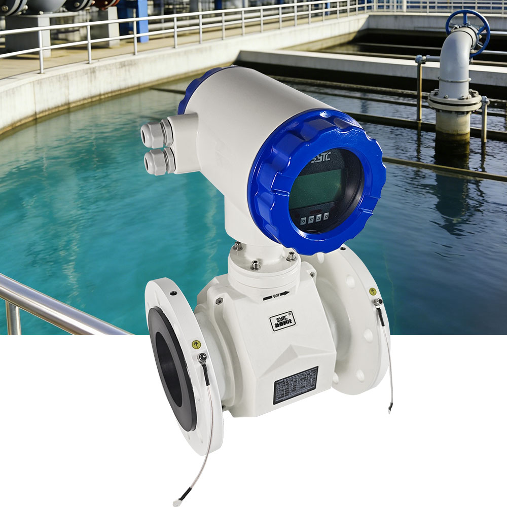
- An electromagnetic flow meter measures liquid volumetric flow rate based on velocity and pipe cross-sectional area. It does not directly measure water quality, dissolved solids concentration, or boiler drum level.
- Boiler control systems (such as blowdown control valves or automatic blowdown controllers) regulate the blowdown process based on setpoints, which may include conductivity or total dissolved solids (TDS) signals from separate water-quality sensors.
- Water-quality monitoring instruments (such as conductivity or TDS analyzers) measure the chemical concentration of the blowdown water but do not measure volumetric flow.
An electromagnetic flow meter can be integrated alongside these instruments — for example, feeding flow data into a plant’s Instrument IoT Big Data Platform for centralized monitoring — but it should not be treated as a substitute for boiler control logic or dedicated water-quality analysis.
Installation and Maintenance Recommendations
- Confirm full-pipe, single-phase liquid conditions at the intended sensor location before finalizing installation.
- Install the sensor with adequate straight pipe runs and proper grounding to maintain signal stability.
- Where remote or hard-to-wire locations are involved, consider split-type or wireless-enabled configurations with real-time data transmission (e.g., RS485, GPRS) to an IoT monitoring platform, allowing centralized visibility of blowdown flow trends.
- Perform periodic inspection of electrodes and lining for scaling, deposit buildup, or wear, particularly if the blowdown stream carries significant dissolved or suspended solids.
- Retain factory-calibrated replacement circuit boards or components as a maintenance strategy to restore accuracy without extended downtime, following manufacturer-recommended procedures.
- Use built-in self-diagnostic alarms (empty pipe, excitation circuit break, flow range overflow) as an operational tool to detect developing issues such as flashing or partial pipe filling before they cause significant measurement errors.
Supplier Evaluation Checklist
When evaluating suppliers for boiler blowdown electromagnetic flow meters, consider:
- Does the supplier provide documented technical standards compliance relevant to electromagnetic flowmeters (such as JB/T 9248-2015) and pipe flange compatibility (such as GB/T 9124.1-2019)?
- Can the supplier confirm actual sensor and converter environmental protection ratings suitable for the installation environment?
- Does the supplier offer engineering support to verify process conditions (temperature, pressure, conductivity, flashing risk) before recommending a specific model?
- Does the supplier provide self-diagnostic features (empty pipe detection, excitation fault alarms) that support ongoing monitoring of measurement reliability?
- Does the supplier offer integration options (RS485, HART, GPRS, or IoT platform connectivity) for centralized data visibility, if required by the facility?
- Does the supplier have documented experience across industrial and municipal metering applications, including material and lining options suited to demanding process fluids?
Kaifeng Xinya Instrument Co., Ltd., as an industrial instrumentation and IoT solutions provider, offers electromagnetic flowmeter product lines (including the SF-E series and specialized configurations) with features such as multi-output signal interfaces, self-diagnosis functions, and IoT platform connectivity, which may be relevant considerations when evaluating instrumentation for demanding process applications such as boiler blowdown monitoring — provided that actual process conditions are verified against the instrument’s technical specifications before final selection.
Frequently Asked Questions
1. Can an electromagnetic flow meter measure boiler blowdown water accurately if flashing occurs?
No. Electromagnetic flow meters measure the velocity of a conductive liquid filling the pipe. If flashing produces vapor within the sensor section, the resulting two-phase or incomplete pipe condition compromises measurement reliability. The installation point should be selected to maintain single-phase, full-pipe liquid flow.
2. Why is conductivity so important for electromagnetic flow measurement in this application?
The electromagnetic measurement principle relies on the induced EMF generated as a conductive fluid moves through a magnetic field. If the liquid’s conductivity is insufficient, or if non-conductive vapor is present, the electrodes cannot generate a reliable signal. Actual process water conductivity should always be verified rather than assumed.
3. What happens if the pipe is not completely full at the sensor location?
Electromagnetic flow meters require full-pipe conditions to generate an accurate signal. Partial filling — often caused by vapor formation or improper installation — leads to inaccurate or unstable readings, and many meters include empty-pipe detection alarms to flag this condition.
4. How is an electromagnetic flow meter different from a boiler blowdown control valve or a TDS analyzer?
A flow meter measures volumetric flow rate only. Blowdown control valves regulate the blowdown process, and water-quality instruments like TDS or conductivity analyzers measure chemical concentration. These are separate functions that may be used together but are not interchangeable.
5. What installation factors most affect flow meter accuracy in blowdown lines?
Key factors include maintaining full-pipe liquid flow, avoiding installation immediately downstream of pressure-reducing valves prone to flashing, proper grounding, and sufficient straight pipe runs upstream and downstream of the sensor.
6. Should sensor lining and electrode materials be selected specifically for blowdown service?
Yes. Lining and electrode material selection should be based on verified process temperature, pressure, and the chemical characteristics of the blowdown water, since generic material choices may not withstand the specific demands of this application.
7. Can blowdown flow data be integrated into a plant monitoring system?
Yes, many electromagnetic flow meters support multiple output signals (such as 4-20mA, pulse, or frequency) and communication protocols (such as RS485, HART, or GPRS), allowing flow data to be transmitted to centralized monitoring or IoT platforms alongside other boiler instrumentation, provided the meter itself is correctly selected and installed for the actual process conditions.
Conclusion
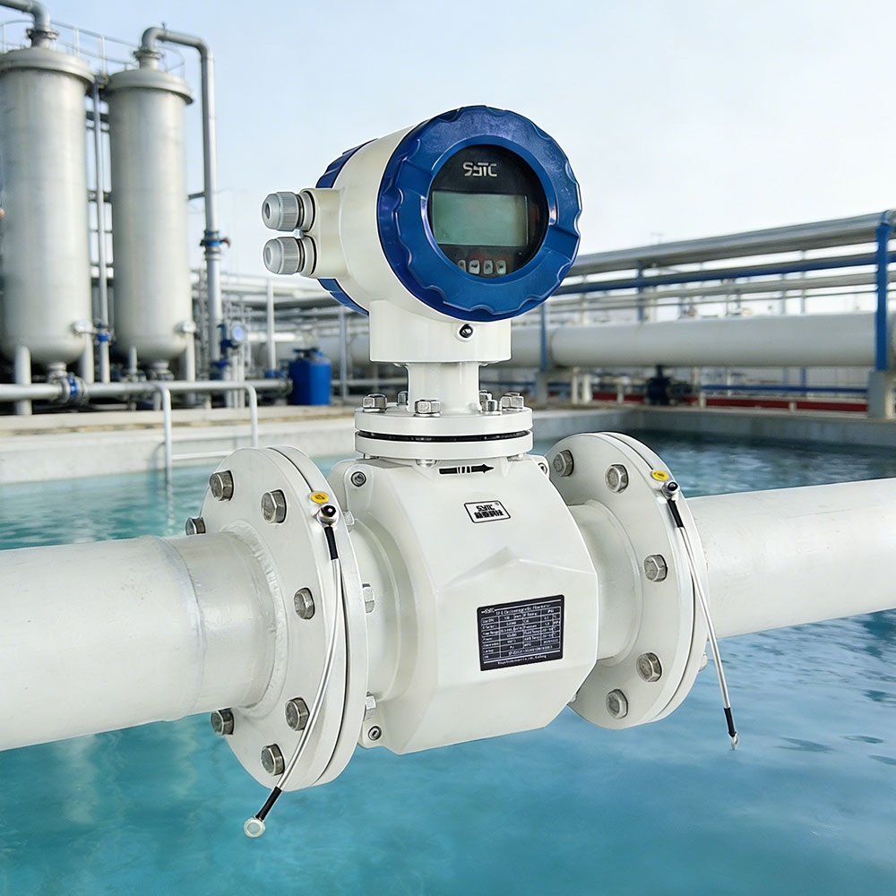
Boiler blowdown water presents a genuinely demanding measurement environment defined by high temperature, elevated pressure, variable conductivity, and a real risk of flashing and two-phase flow as pressure is reduced downstream of the boiler. Electromagnetic flow meters can be a suitable technology for this duty, but only when actual process conditions — temperature, pressure, conductivity, and flashing risk — are verified and matched against the instrument’s engineering limitations, material selection, and installation requirements. Treating boiler blowdown as an ordinary low-temperature water application, or overlooking the fundamental dependency on liquid conductivity and full-pipe flow, is the most common source of measurement failure in this application. Careful selection, correct installation, proper grounding, and appropriate calibration remain the foundation for reliable flow measurement in this critical boiler system function.
https://www.sytcflowmeter.com/
Kaifeng Xinya Instrument Co., Ltd.
