
Electromagnetic Flow Meter for Data Center Cooling Water Systems
Introduction
Data center cooling infrastructure depends on continuous, accurate visibility into water flow across chilled-water loops, cooling distribution networks, and heat exchanger circuits. Because most data center cooling systems circulate treated conductive water, electromagnetic flow meters are a widely used measurement technology for these applications. This article examines where and why electromagnetic flow meters are applied in data center cooling water systems, the technical parameters that determine correct selection, and common installation and operational issues that facility, HVAC, and instrumentation engineers should evaluate.
Why Electromagnetic Flow Meters Suit Conductive Cooling Water
Electromagnetic flow meters operate on Faraday’s principle of electromagnetic induction: a magnetic field is generated across the flow tube, and the movement of a conductive liquid through this field induces a voltage proportional to velocity. This measurement principle is well matched to data center cooling water because:
- Conductive medium requirement: Chilled water, glycol-water mixtures (above a minimum conductivity threshold), and treated cooling water are electrically conductive, satisfying the basic requirement for electromagnetic measurement.
- No moving parts in the flow path: The sensor has no mechanical components inside the pipe, which is relevant for continuous, unattended operation typical of cooling plants that run around the clock.
- Bidirectional capability: Electromagnetic flow meters can track forward and reverse flow, which is useful in loops where flow direction may reverse due to pump switching, valve sequencing, or variable-flow control strategies.
- Wide velocity range: Many electromagnetic flow meters, including those built to standards such as JB/T9248-2015, support velocity ranges from approximately 0.1 to 10 m/s, covering both low-flow secondary loops and higher-velocity primary distribution mains.
Where Flow Measurement Is Required in Data Center Cooling Infrastructure
Flow measurement points are typically distributed across several functional zones of the cooling plant:
Chilled-Water Supply and Return
Measuring flow at the chilled-water supply and return headers of each chiller or air handling loop allows facility teams to verify design flow rates, detect flow imbalance between units, and support delta-T based performance checks (in conjunction with temperature sensors).
Primary Cooling Loops
Primary loops connect chillers to the plant distribution system. Flow meters here validate chiller-side flow rates against manufacturer specifications and support primary-secondary loop decoupling verification.
Secondary Cooling Loops
Secondary loops distribute cooling to individual data hall zones, CRAH/CRAC units, or in-row cooling units. Flow measurement at this level supports zone-level balancing and helps identify under- or over-served cooling zones.
Cooling Distribution Piping
Larger distribution mains, sometimes up to very large nominal diameters in hyperscale facilities, may use insertion-type electromagnetic flow meters where full-bore meters would be costly or difficult to install without interrupting flow.
Heat Exchanger Circuits
Both primary and secondary sides of plate or shell-and-tube heat exchangers benefit from flow verification to confirm heat transfer conditions are within design parameters.
Cooling Plant Flow Monitoring
Plant-level totalized flow monitoring supports overall capacity planning, pump staging decisions, and integration with building automation systems (BAS) or data center infrastructure management (DCIM) platforms.
Key Technical Parameters for Selection
Correct electromagnetic flow meter selection for cooling water applications requires evaluating the following parameters together, not in isolation:
- Water conductivity: Standard treated cooling water and chilled water are generally conductive enough for electromagnetic measurement; glycol concentration and water treatment chemistry should be checked against the meter’s minimum conductivity specification.
- Flow range: The expected minimum and maximum flow rates should fall within the meter’s rated velocity range (commonly around 0.1–10 m/s) to maintain measurement accuracy across operating conditions, including part-load periods.
- Pipe diameter: Nominal diameter must match the piping design; electromagnetic flow meters are available across a wide range of sizes, from small branch lines to large distribution mains (e.g., DN15 up to DN3000 in some product lines), and insertion-type meters are an option for very large pipes.
- Temperature: The meter’s liner and electrode materials, as well as the converter housing, must be rated for the chilled or condenser water temperature range at the installation point.
- Pressure: Flange rating and body materials must be compatible with system operating pressure, including transient pressure during pump start/stop events.
- Flow velocity: Both minimum detectable velocity and maximum recommended velocity affect accuracy class selection (commonly offered as ±0.5%, ±0.3%, or ±0.2% depending on application requirements).
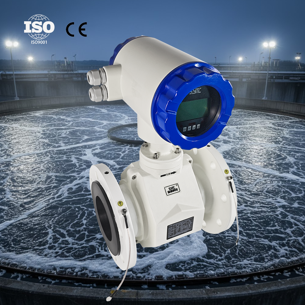
- Full-pipe conditions: Electromagnetic flow meters require the pipe to remain fully filled with liquid at the measurement point; installation should avoid locations where partial filling or air pockets are likely.
- Installation location: Adequate straight-pipe run upstream and downstream of the sensor, away from pumps, elbows, valves, and other flow disturbances, is required for stable readings.
- Grounding: Proper grounding of the sensor and pipeline is required to avoid stray electrical interference affecting the induced signal; grounding rings or grounding electrodes are used depending on pipe material (e.g., non-conductive linings or plastic pipe).
- Protection rating: Converter housings are commonly rated IP65/IP66/IP67 for standard installations, while submersible or buried sensor applications may use IP68-rated sensor housings.
- Calibration: Flow meters should be selected with documented calibration and, where applicable, factory-calibrated replacement components to maintain accuracy over the service life of the instrument.
Flow Measurement vs. Cooling Capacity and Energy Measurement
It is important to distinguish flow measurement from cooling capacity or thermal energy measurement:
- An electromagnetic flow meter measures volumetric flow rate (and, with a pulse/frequency or 4-20mA output, cumulative volume) — it does not by itself measure how much cooling or heat energy is being delivered.
- Thermal energy (cooling capacity) measurement requires combining the flow rate with a temperature differential between supply and return water, using appropriately paired temperature sensors and an enthalpy or heat calculation function.
- Some electromagnetic flow meter and controller combinations include heat measurement functionality based on enthalpy difference (Δh) calculations, but this functionality depends on integrating accurate temperature inputs alongside the flow signal — it is not inherent to the flow meter alone.
Facility teams should ensure that any energy management or BAS reporting that references "cooling load" or "kWth" is built on both a properly installed flow meter and correctly located, calibrated temperature sensors.
How Flow Measurement Supports Cooling Control and Energy Management
Reliable flow data feeds several operational functions in data center cooling systems:
- Cooling system balancing: Comparing flow rates across parallel chillers, loops, or CRAH units helps identify imbalance that can lead to some zones being under-cooled while others are over-cooled.
- Control loop feedback: Variable-speed pumping and valve control strategies often use flow signals (commonly 4-20mA, pulse, or frequency outputs) as feedback variables.
- Monitoring and alarming: Continuous flow monitoring, especially when integrated into an IoT or BAS platform, allows facility teams to detect abnormal conditions such as sudden flow loss, valve failure, or pump issues.
- Energy management context: When paired with temperature data, flow measurement is a foundational input for calculating delivered cooling energy, which supports capacity planning and load distribution decisions — though flow data alone does not constitute energy measurement.
- Data logging and trending: Many electromagnetic flow meter and converter systems support internal data logging (for example, extended monthly totalization records) and remote access via RS485, HART, GPRS, Bluetooth, or WiFi, and can be integrated with a cloud-based platform for historical trend analysis and remote diagnostics.
Common Problems in Data Center Cooling Water Flow Measurement
Air Entrainment
Air bubbles introduced by pump cavitation, poorly designed expansion tanks, or turbulent return piping can cause fluctuating or inaccurate readings, since electromagnetic flow meters are designed for fully liquid-filled pipes.
Partially Filled Pipes
Horizontal runs near open discharge points, poorly vented high points, or gravity-return sections may not remain full, leading to erroneous low-flow or erratic signals. Vertical installation with upward flow, where feasible, or relocation to a location guaranteed to remain full, is a common mitigation.
Low Conductivity from Water Treatment
Some water treatment chemistries, deionized water systems, or high-glycol mixtures can reduce conductivity below the meter’s minimum threshold, degrading signal quality. Conductivity should be verified against manufacturer specifications during design.
Pump-Induced Turbulence
Installing a flow meter too close to a pump discharge, especially without sufficient straight-pipe run, can introduce turbulent flow profiles that reduce measurement repeatability.
Poor Grounding
Inadequate grounding, especially in plastic-lined or non-metallic piping, can allow electrical noise to interfere with the low-level induced voltage signal, causing unstable readings.
Incorrect Sizing
Oversized meters relative to actual flow rates can result in operation near the low end of the velocity range, where accuracy typically degrades; undersized meters may create excessive pressure drop or exceed maximum recommended velocity.
Flow Fluctuations
Rapid changes in flow due to valve modulation, staged pump control, or variable-flow secondary loops can be captured more effectively by meters with adequate signal processing and update rates; specification of response characteristics should match the control system’s requirements.
Installation Near Unsuitable Piping Configurations
Locating the meter immediately downstream of tees, reducers, control valves, or multiple elbows in different planes without adequate straight-run distance is a frequent cause of measurement instability and should be avoided during piping design.
Why No Moving Parts Can Be Beneficial
Because the measurement principle relies on electromagnetic induction rather than mechanical elements such as turbines, paddlewheels, or vortex-shedding bodies, electromagnetic flow meters do not have components inside the flow path that are subject to mechanical wear from continuous operation. This characteristic can be relevant for cooling water applications that operate continuously, since it removes certain wear-related failure modes associated with moving mechanical parts. This does not imply that electromagnetic flow meters are maintenance-free; periodic verification, cleaning of electrodes in fouling-prone applications, and calibration checks remain part of a sound maintenance program.
Selection Checklist for Data Center Cooling Applications
- Confirm minimum water conductivity against the meter’s specification, particularly for glycol or treated-water systems.
- Match pipe diameter and required accuracy class to the loop’s design flow range.
- Verify temperature and pressure ratings against the specific supply/return, primary, or secondary loop conditions.
- Select an installation location with adequate straight-pipe run, away from pumps and fittings.
- Specify grounding provisions appropriate to the pipe material.
- Choose a protection rating matching the installation environment (indoor mechanical room vs. buried or submerged application).
- Confirm calibration documentation and traceability before commissioning.
- Determine whether integration with a BAS, DCIM, or IoT platform is required, and confirm available communication protocols (such as RS485, HART, GPRS, or MODBUS-RTU).
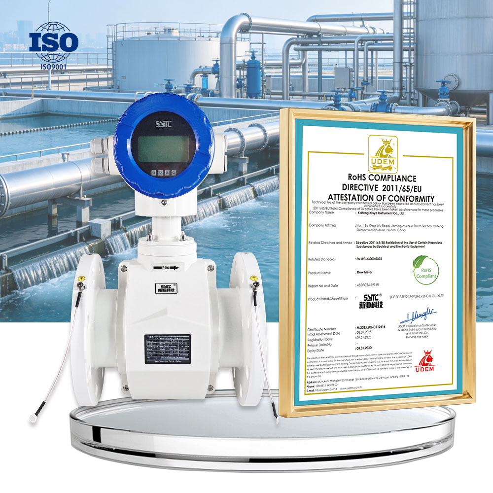
Suppliers such as Kaifeng XinYa Instrument Co., Ltd. offer electromagnetic flow meter product lines — including standard industrial types, insertion-type meters for large pipe diameters, and battery-powered/split-type configurations — that can be evaluated against the parameters above during the specification process for data center cooling water applications. Selection should always be based on the specific project’s flow range, pipe size, water chemistry, and installation constraints rather than on a single default model.
Frequently Asked Questions
Q1: Can an electromagnetic flow meter measure flow in a chilled-water glycol loop?
It depends on the glycol concentration and resulting conductivity. Electromagnetic flow meters require the fluid to be electrically conductive; very high glycol concentrations can reduce conductivity to a point that affects measurement, so this should be verified against the specific meter’s minimum conductivity specification.
Q2: Does an electromagnetic flow meter measure cooling capacity in kW or tons?
No. An electromagnetic flow meter measures volumetric flow rate. Cooling capacity or thermal energy calculations require combining flow rate with a supply/return temperature differential using appropriately installed temperature sensors and a heat calculation function.
Q3: Where should flow meters be installed relative to pumps in a cooling loop?
Flow meters generally should not be installed immediately at a pump discharge or suction. Sufficient straight-pipe run upstream and downstream, as specified by the meter manufacturer, is needed to avoid turbulence-related measurement error.
Q4: What happens if the pipe is not completely full at the flow meter location?
Electromagnetic flow meters are designed for full-pipe conditions. A partially filled pipe can result in inaccurate or unstable readings, since the measurement principle assumes the entire cross-section is occupied by conductive liquid.
Q5: Can electromagnetic flow meters be used on very large cooling distribution mains?
Yes, in principle. Full-bore electromagnetic flow meters are available across a wide range of diameters, and insertion-type electromagnetic flow meters are an alternative for very large pipe diameters where installing a full-bore meter is impractical or costly.
Q6: Is grounding really necessary for an electromagnetic flow meter?
Yes. Because the meter detects a small induced voltage signal, inadequate grounding — particularly in non-metallic or lined piping — can introduce electrical noise that affects measurement stability and accuracy.
Q7: How often should a cooling-water electromagnetic flow meter be recalibrated?
Recalibration intervals depend on the application, water quality, and site conditions. Facility teams should follow the manufacturer’s recommended calibration schedule and verify performance periodically as part of routine instrumentation maintenance, rather than assuming indefinite accuracy without verification.
Summary
Electromagnetic flow meters are a technically appropriate measurement solution for the conductive water circuits found throughout data center cooling infrastructure — from chilled-water supply and return lines to primary and secondary loops, distribution piping, and heat exchanger circuits. Reliable application depends on correctly analyzing water conductivity, flow range, pipe diameter, temperature, pressure, velocity, full-pipe conditions, installation location, grounding, protection rating, and calibration requirements. Flow measurement should be understood as one input — alongside temperature measurement — for broader cooling control, balancing, monitoring, and energy management functions, rather than a standalone energy metering solution. Careful attention to installation practices and awareness of common issues such as air entrainment, partial fill, low conductivity, and turbulence will support more consistent flow measurement performance across data center cooling water systems.
https://www.sytcflowmeter.com/
Kaifeng Xinya Instrument Co., Ltd.
