
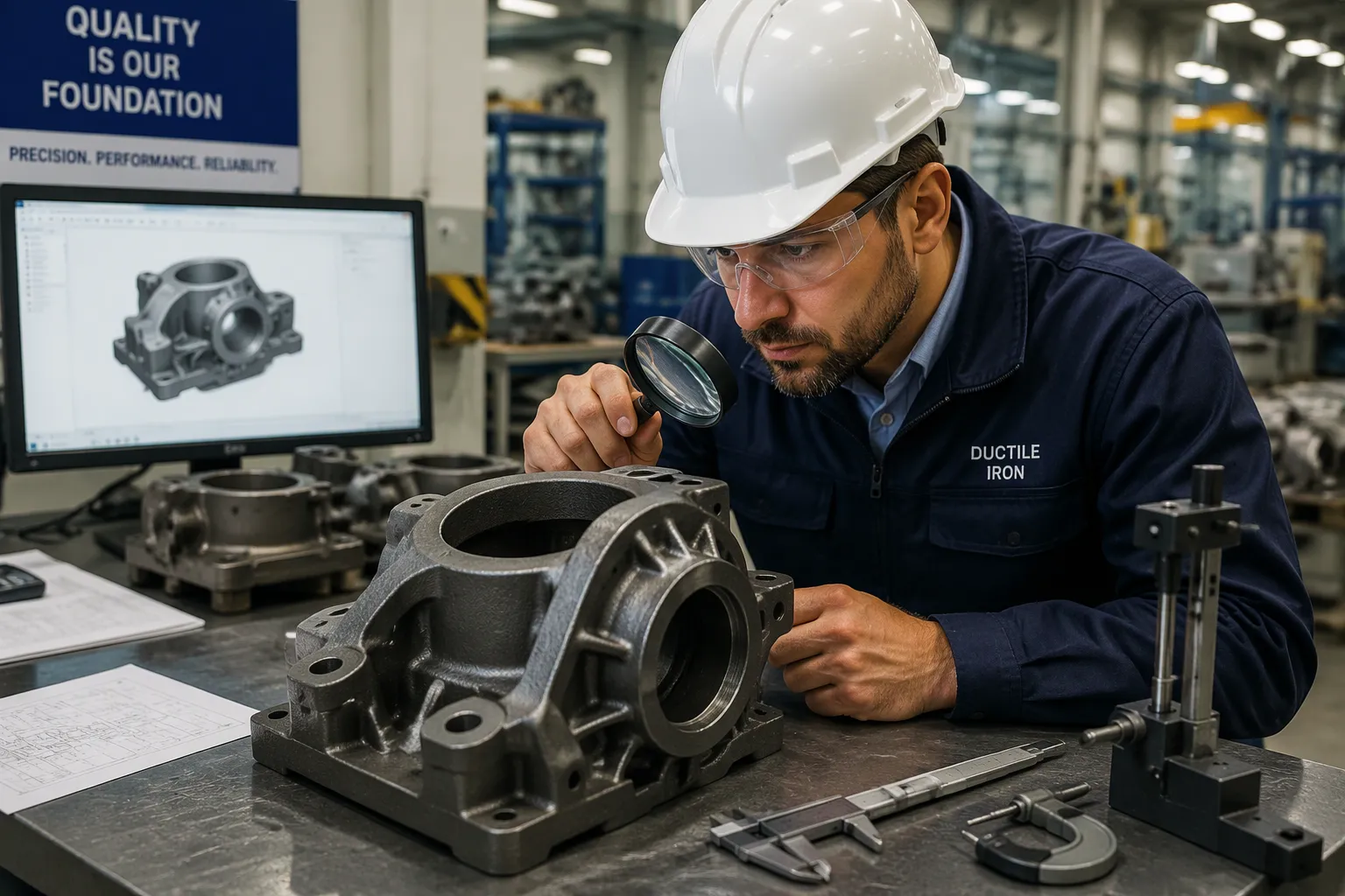
Four core rules govern ductile iron casting design: uniform wall thickness, generous fillets and radii, proper draft angles, and early foundry engagement. These rules control solidification uniformity and avoid stress concentration. Ductile iron’s graphite nodules make the material forgiving, but design determines whether that potential is realized. Engineers should create an approximately 1 mm machining allowance on critical surfaces.
Key Takeaways
- Keep wall thickness uniform to avoid shrinkage and ensure strong castings.
- Use generous fillets and radii to reduce stress and prevent defects.
- Engage your foundry early to catch design issues before tooling costs rise.
Wall Thickness: The Primary Design Variable
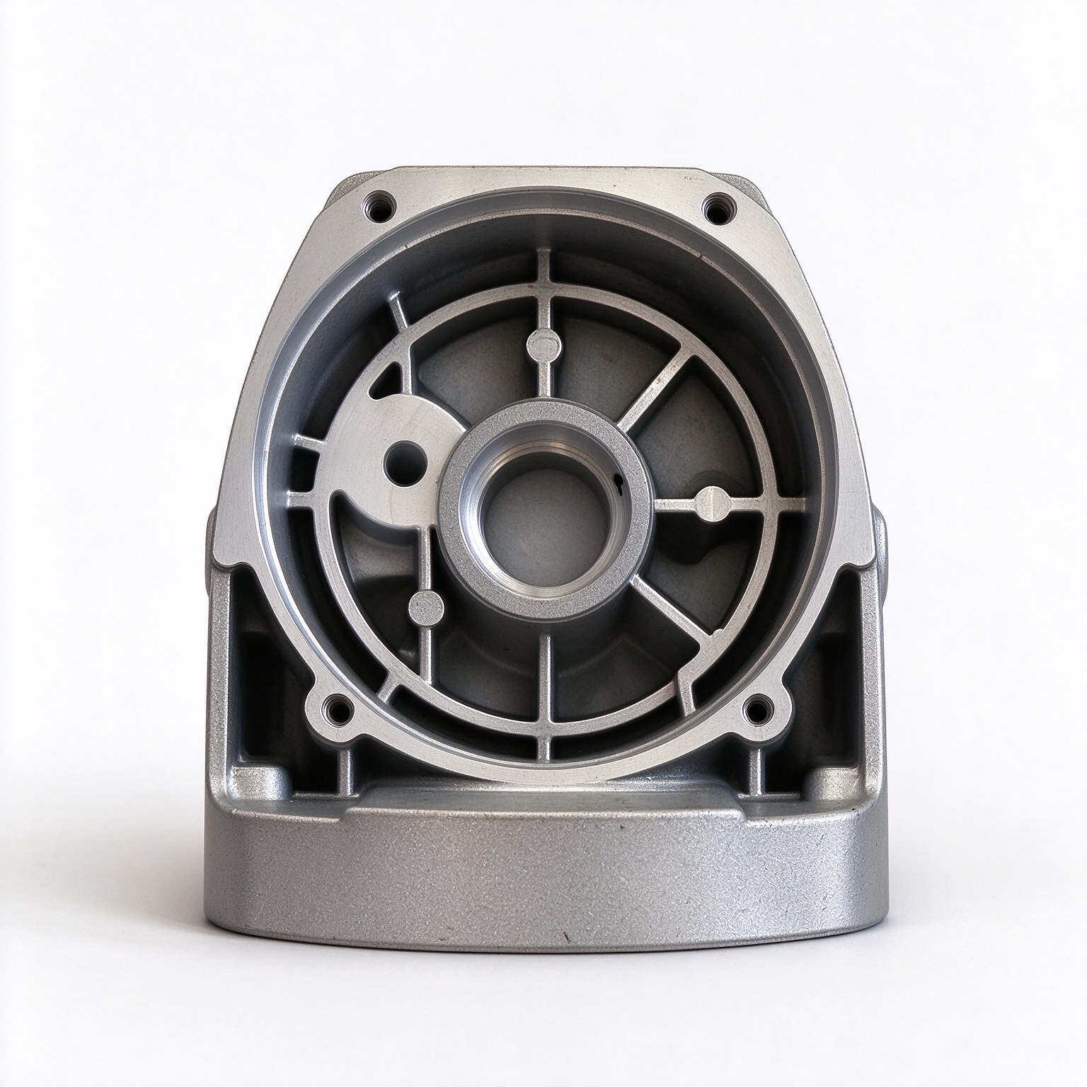
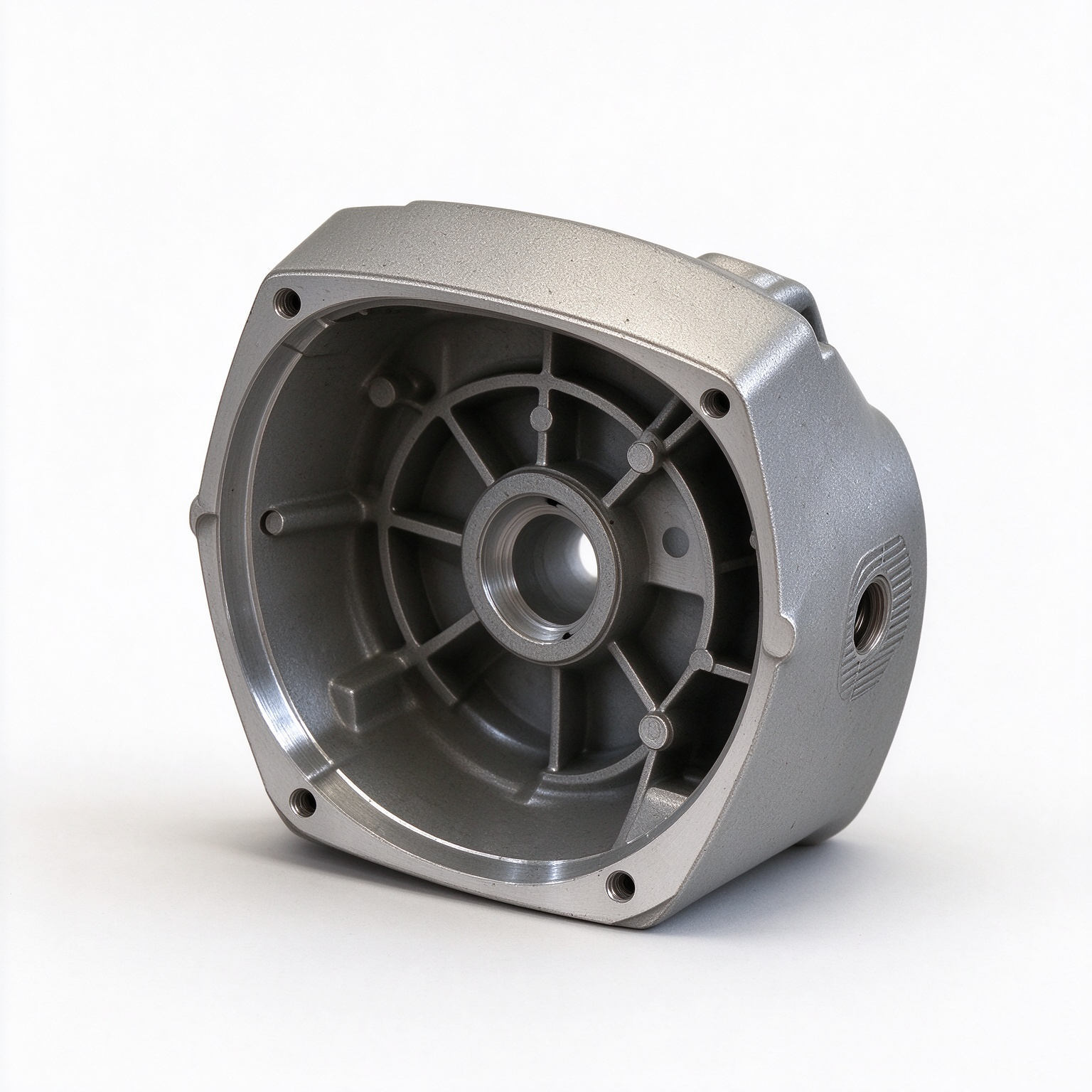
Wall thickness is the single most influential decision in a ductile iron casting drawing. It sets the cooling rate, the solidification pattern, the resulting microstructure, and the defect risk profile of the entire part. A designer who controls wall thickness controls most of what happens inside the mold. Every other design feature works around this foundation.
How Wall Thickness Controls Cooling Rate and Microstructure
Molten iron loses heat through the mold wall. A thin section sheds heat quickly, so it solidifies fast. A thick section holds heat longer, so it solidifies slowly. This difference in cooling rate directly shapes the final microstructure.
Fast cooling produces a finer graphite nodule structure and a harder matrix. Slow cooling produces coarser nodules and can promote pearlite or carbide formation, depending on the chemistry and section size. Both outcomes are legitimate. The problem arises when both occur in the same casting at the same time.
Uneven cooling creates a thermal gradient across the part. The thin region solidifies first and stops accepting feed metal. The thick region remains liquid and continues to shrink. With no liquid channel left to feed it, the thick region pulls a void. That void becomes shrinkage porosity, and it usually sits deep inside the section where no machining operation can reach it.
Wall thickness also governs the mechanical properties that the designer specifies. A QT450-10 base, for example, achieves its rated tensile strength of at least 450 MPa and elongation of at least 10 percent only when the casting cools at a rate that produces the intended nodular structure. A section that cools too slowly may miss the elongation target. A section that cools too fast may develop chill or carbides that reduce machinability. The drawing must give the foundry a wall thickness that supports the specified grade.
Minimum Wall Thickness Guidelines
Ductile iron flows well, but it still needs a minimum section size to fill reliably and to develop sound metal. Industry practice converges on a practical floor. Farrar USA recommends a minimum section thickness of 0.300 inches, with more allowance for larger parts or complex core layouts. Hiler Industries gives the same 0.300-inch figure and ties it to two outcomes: proper metal flow into the mold and overall structural integrity of the finished component.
These guidelines apply to general industrial castings. They are not universal constants. Several factors push the minimum upward:
- Larger castings need thicker walls because heat loss paths are longer and feed distances increase.
- Complex core layouts restrict metal flow and call for additional section thickness.
- Long, thin projections and isolated bosses cool faster than the surrounding mass and may need local thickening.
- Aggressive machining allowances can reduce a nominal wall below the sound-metal threshold.
Pipe design offers a useful illustration of how engineers build minimum wall thickness from first principles. The AWWA C150 design standard evaluates internal pressure containment, bending stress, and deflection separately, then adopts the worst-case result as the governing design. Casting tolerance and a service allowance are added on top. For an 8-inch ductile iron pipe at 150 psi working pressure, the net pressure thickness is 0.05 inches. Adding casting tolerance and the standardized 0.08-inch service allowance brings the required manufactured thickness to 0.20 inches. The same logic appears in a 24-inch example, where bending stress governs:
| Design Check (24-inch pipe) | Net Thickness | Service Allowance | Casting Tolerance | Total |
|---|---|---|---|---|
| Internal pressure | 0.15 in | 0.08 in | 0.07 in | 0.30 in |
| Bending stress | 0.20 in | 0.08 in | 0.07 in | 0.35 in |
| Deflection | 0.18 in | 0.08 in | 0.07 in | 0.33 in |
Bending stress governs at 0.35 inches, and the first available wall class meeting that figure is Pressure Class 250. The lesson transfers to general castings. A designer should calculate the structural minimum, then add machining stock and casting tolerance rather than starting from a nominal number and hoping it holds.
Rules for Uniform Wall Thickness
Uniformity is the goal, not absolute equality. A casting with one wall thickness everywhere is rarely possible and often unnecessary. The practical rule is to keep adjacent sections as close in thickness as the function allows.
Farrar USA and Hiler Industries both state the core principle plainly: keep wall sections as uniform as possible and avoid abrupt changes in thickness. A designer can apply this rule through a few working habits:
- Establish a nominal wall for the part and hold most of the geometry to it.
- Thicken thin ribs and bosses to within roughly one section thickness of the surrounding wall.
- Place ribs on the thick side of a junction rather than the thin side.
- Check every isolated feature, such as a mounting lug or a bolt pad, against the nominal wall.
- Review the drawing for any section that departs from nominal by more than a factor of about two.
A useful sanity check is to trace heat flow through the part. Any location where two or more walls meet behaves as a thicker section, because the junction contains more mass than either wall alone. Designers should treat junctions as hot spots and adjust nearby geometry accordingly.
Managing Thick-to-Thin Transitions
Some transitions are unavoidable. A heavy mounting flange must connect to a lighter body. A bearing boss must rise from a thinner housing wall. The design question is not whether transitions exist but how they are shaped.
IQS Directory notes that thick-to-thin transitions cause uneven cooling, and uneven cooling leads to shrinkage, porosity, and internal stress. Rapid cross-sectional changes produce non-uniform cooling that drives shrinkage, hot tears, and warping. The recommended remedy is consistent: uniform wall sections with generous radii and tapers at every transition.
A taper spreads the change in mass over a longer distance. Instead of stepping from 0.75 inches to 0.30 inches at a single plane, the designer ramps the thickness down over a length several times the thickness difference. The gradual change lets the thin end solidify progressively while the thick end still receives feed metal. The result is directional solidification rather than isolated hot spots.
Ductile iron shrinks as it solidifies, and uniform wall thickness helps ensure that shrinkage is eliminated or at least relocated to a riser. IQS Directory also points out that designs should allow dimensional increases in a consistent manner, with risers positioned to feed the metal that the thicker sections need. The designer’s job is to make that feeding path possible. A well-tapered transition gives the foundry a clear path to place a riser and a clear direction for solidification to progress.
Three practical rules cover most transition cases:
- Use a taper rather than a step whenever the thickness ratio exceeds about 1.5 to 1.
- Keep fillet radii at the transition generous, typically at least the thickness of the thinner section.
- Avoid isolated heavy sections surrounded by thin walls, because no riser can feed them without a path.
A designer who applies these rules gives the foundry a casting that solidifies in a predictable sequence. That predictability is what separates a drawing that produces sound castings from one that produces scrap.
Structural Design Features That Protect Integrity

Wall thickness sets the thermal foundation of a casting. The features built on top of that foundation determine how the part carries load and how the mold fills. Fillets, draft, cores, and machining stock each address a specific failure mode. A designer who treats them as afterthoughts leaves quality to chance. A designer who specifies them deliberately removes risk before the pattern is ever cut.
Fillets and Radii: Avoiding Stress Concentrators
A sharp internal corner is a stress raiser by geometry alone. Load lines crowd into the corner, and the local stress climbs far above the nominal stress in the surrounding section. Neural Concept explains that sharp corners and notches cause localized stress through abrupt changes in geometry. The site notes that a sharp corner increases the stress concentration factor, while larger fillet radii reduce it. The effect is not subtle. Inglis quantified it in 1913 for an elliptical hole, where the stress concentration factor equals 1 + 2a/b, with a and b as the semi-axes. The factor rises without limit as the root radius sharpens toward zero.
A fillet solves this problem at the drawing stage. Atlas Foundry & Manufacturing lists three functional purposes for fillets: reducing in-service stress concentration, eliminating cracks and tears at reentry angles, and making corners more moldable by removing hot spots. The third purpose matters as much as the first two. A sharp corner holds a pocket of hot metal that cools last, and that hot spot becomes a shrinkage site. A generous radius spreads the mass and lets heat leave evenly.
Fillet sizing follows a few practical rules:
- Use the minimum number of distinct radii in one pattern, preferably only one, so the pattern shop and the molder work to a single standard.
- Size the fillet radius to at least the thickness of the casting section where engineering stress demands it.
- Cap the fillet radius at half the thickness of the section joined, because an oversized fillet adds mass and creates its own hot spot.
- Round the outside corner of an L-junction to match the inside fillet, so the junction does not become a thick section.
- Apply a generous radius to V, Y, and other angular forms to prevent heat localization.
The balance point deserves emphasis. A fillet that is too small concentrates stress. A fillet that is too large adds a heavy mass at the junction and invites shrinkage. The workable window sits between those extremes, and the section thickness defines both ends of it.
Abrupt cross-section changes behave like sharp corners in a different guise. Neural Concept notes that sudden thickness transitions cause stress spikes, and the magnitude depends on the ratio of the fillet radius to the smaller dimension. A shoulder blended with a generous radius carries the same load at a much lower peak than a square step. The designer’s habit should be simple: never let two surfaces meet at a sharp angle, and never let a section change without a blend.
Draft Angles for Clean, Sound Castings
Draft is the taper applied to every surface that runs parallel to the direction of pattern withdrawal. Without draft, the pattern drags against the mold wall during extraction. The drag tears sand, opens the mold surface, and leaves a rough cavity that fills with defects. A drafted surface releases cleanly, and the mold stays intact.
Draft also protects the casting itself. A pattern that sticks in the sand distorts the cavity, and a distorted cavity produces a casting that misses its dimensional targets. The taper is small, typically a degree or two per side, but its effect on surface finish and dimensional consistency is large. Designers should apply draft to every vertical wall, boss, and rib, and they should apply it in the direction the pattern actually moves. A feature that needs draft in two directions usually signals a design that needs simplification.
The draft requirement interacts with wall thickness. A thin wall with no draft may survive extraction in a forgiving sand, but the same wall with proper taper fills more reliably and cools more evenly. Draft is cheap to add at the drawing stage and expensive to correct after tooling exists.
Core Design and Simplification
Cores create internal passages and undercuts that the pattern cannot form. They also introduce some of the most common defect sources in a ductile iron casting. A core generates gas as its binder burns during filling. That gas must escape, or it builds back-pressure against the incoming metal. Phenix Foundry notes that section thickness, fillet radii, draft, machining stock, and core design all influence casting quality and consistency. Reviewing these elements early lets the team address manufacturing challenges before tooling is produced, when changes are simpler and less expensive.
A differential housing case study from ZHY Casting shows how core design drives outcomes. The initial design poured slowly at 13 to 16 seconds against a simulated target of about 8 to 9 seconds. Analysis traced the delay to gas back-pressure from a voluminous core. Burning binder generated gas faster than it could escape, and the gas resisted metal flow. The multi-stage gating system added metallic weight and pulled process yield down to 36.7 percent.
The optimized design attacked both problems at once:
| Process Metric | Initial Design | Optimized Design |
|---|---|---|
| Pouring time (actual) | 13–16 s | 10.2–10.3 s |
| Simulated pouring time | ~8–9 s | ~8.5 s |
| Process yield | 36.7% | 42.7% |
| Gating complexity | High (multi-stage splice) | Moderate (simplified, top-fed risers) |
| Venting | Standard | Enhanced with vent sheets |
The team added vent sheets to the horizontal runner, giving core gas an easy path to atmosphere. They eliminated the two vertical runner sections, slimmed the horizontal runner, and repositioned the ingates to feed directly into the top of the risers. A step-gate connection preserved the slag-trapping benefit. Recalibrated choke areas held the filling speed under control with the simpler layout. In a monitored batch of 1,887 castings, the foundry reject rate came in at 3.29 percent, a 96.71 percent acceptance rate. Machining rejects for casting-related internal porosity stayed below 1 percent.
A gating system designed for low turbulence must be paired with effective venting, particularly when large cores are present, to ensure predictable fill times and avoid gas-related defects.
The design lesson is direct. Every core adds a gas source, a locating requirement, and a cost. A designer should ask whether the internal passage is truly needed, whether an open section could replace it, and whether the core can be simplified. Fewer cores mean fewer gas paths, fewer core shifts, and a more predictable fill. Simplification is not a compromise on function. It is a quality control measure applied at the drawing stage.
Machining Stock and Dimensional Control
Casting tolerances and machining stock work together to guarantee that the finished part meets its drawing. Ductile iron castings carry dimensional variation from pattern wear, mold compaction, and solidification shrinkage. Xuxiangtai works to GB/T 6414 CT8 to CT10 tolerance grades, which sets the expected variation band for a given size. The designer must plan for that band.
Machining stock is the layer of metal left on a surface that will be cut. The stock must cover the worst-case combination of casting tolerance, draft, and distortion. Too little stock leaves the machinist chasing a surface that never cleans up. Too much stock wastes metal, adds machining time, and can push a thin wall below its sound-metal threshold. The practical target for critical surfaces is approximately 1 mm of allowance, adjusted upward for large parts and for surfaces that sit far from the datum.
Dimensional control starts with datum selection. The designer should choose datums that the foundry can hold and the machinist can locate against. A datum that depends on a drafted surface or a cored hole introduces stack-up error into every downstream operation. A datum tied to a machined pad or a stable boss keeps the tolerance chain short.
The machining allowance also interacts with wall thickness. A 1 mm cut on a 6 mm wall removes a sixth of the section. The designer should verify that the nominal wall plus the allowance still meets the structural minimum, and that the finished wall stays above the sound-metal floor. This check belongs on the drawing review, not on the shop floor.
Fillets, draft, core simplification, and machining stock are not decorative details. Each one closes a specific defect path. Each one is far cheaper to specify at the drawing stage than to correct after the first castings fail inspection.
Designing Out Defects and Collaborating with Your Foundry
Wall thickness and structural design determine whether a ductile iron casting solidifies soundly or carries hidden defects. Uniform walls promote even cooling and consistent microstructure. Structural features control stress and defect risk. Designers who address both at the drawing stage remove most quality problems before tooling begins.
Shrinkage Porosity: Design for Directional Solidification
Directional solidification prevents shrinkage porosity by sequencing freezing from thin sections toward the riser. Foundrymax explains that thin sections freeze first, thick sections freeze last, and feed metal flows toward the heaviest mass. Shrinkage cannot form when liquid metal replaces what contracts. Sefu notes the optimal thermal sequence:
- Thin sections solidify first.
- Thick sections draw feed metal next.
- Risers solidify last.
Designers should taper wall transitions in steps, aim gating at heavy sections, and place risers to freeze last. Chills cut solidification time in targeted zones and force the desired sequence.
Hot Tears and Distortion: Design for Restrained Contraction
Hot tears and distortion arise from thermal stress during solidification. ZHY Casting reports that high thermal gradients cause warping, while constrained contraction causes hot tears at junctions. The corrective measures differ by defect:
| Defect | Likely Cause | Corrective Measure |
|---|---|---|
| Distortion | High thermal gradients | Use chills on thick sections, lower pour temperature |
| Hot tears | Constraint stress at junctions | Add fillets, use flexible mold coatings, reduce cooling rate |
For uniform or thin-walled parts, simultaneous solidification minimizes temperature gradients and reduces thermal stress. Ductile iron demands a stricter tolerance than gray iron because graphite expansion behaves differently.
Gas and Inclusion Defects: Design for Clean Filling
Clean filling depends on controlled, tranquil metal flow. SF Foundry recommends runner extensions beyond the last gate to trap dirty metal, ceramic filters in runners or sprue wells, and unpressurized bottom gating with gate velocities below 0.5 m/s. Gates placed too near the runner end receive the dirtiest metal, so designers should maintain distance from the runner end to the first gate. Rounded runner corners prevent low-pressure regions that draw in air. InTouch Quality adds that good venting, dry molds, and adequate sand permeability prevent gas porosity. Slag inclusions require fluxing, bottom-pour ladles, or ceramic filters.
Early Design Review and Simulation
Early review is the most economical quality control available. Bowmanville Foundry notes that changing the original part design is the most economical approach in the manufacturing chain. Designers should map loads, mark geometric interruptions, revise transitions, and compare simulation results before tooling is fixed. Simulation connects geometry, material behavior, and cooling history to predicted stress and dimensional change. A useful design package links the CAD model with material requirements, service loads, and critical interfaces. Foundry teams should review geometry, loading, and performance requirements together.
Create an approximately 1 mm Machining Allowance for Critical Surfaces
Machining stock must cover casting tolerance, draft, and distortion. Designers should create an approximately 1 mm allowance on critical surfaces, adjusted upward for large parts. Create an approximately 1 mm allowance that keeps the finished wall above the sound-metal floor. Create an approximately 1 mm allowance on datum surfaces to keep the tolerance chain short. Create an approximately 1 mm allowance and verify it against the structural minimum. Create an approximately 1 mm allowance before finalizing the drawing. Qingdao Xuxiangtai Machinery Manufacturing Co., Ltd. supports custom mechanical parts manufacturing and OEM services for industrial applications, producing to customer drawings, samples, and technical specifications. International buyers can submit drawings, samples, or technical requirements for custom casting and machining inquiries.
Uniform walls, generous radii, correct draft, and early foundry involvement remain the four rules that govern sound ductile iron design. Wall thickness drives solidification and microstructure; structural features control stress and defect risk. ZHY Casting reports that drawing-stage simulation on a ductile iron cover cap cut trial costs by roughly 80% and scrap from 15% to under 2%.
| Design decision | Cost-effectiveness evidence |
|---|---|
| Cover cap ingate changed from 8 mm to 10 mm at drawing stage | Trials reduced from five to one; development cycle shortened from two months to three weeks; scrap fell from 15% to under 2% |
Qingdao Xuxiangtai Machinery Manufacturing Co., Ltd. supports custom mechanical parts manufacturing and OEM services for industrial applications, producing to customer drawings, samples, and technical specifications. International buyers can submit drawings, samples, or technical requirements for custom casting and machining inquiries.
FAQ
What minimum wall thickness should a ductile iron casting use?
Designers should target at least 0.300 inches for general industrial castings. Larger parts, complex cores, and heavy machining stock push that floor upward.
How large should a fillet radius be?
A fillet should match the thinner section’s thickness. Designers should cap it at half the joined section’s thickness to avoid adding a hot spot.
When should a designer contact the foundry?
Designers should engage the foundry during the drawing stage. Early review catches wall transitions, core problems, and draft issues before tooling costs lock in.
See Also
How To Avoid Selecting The Incorrect Aluminum Casting Process Ever Again
https://www.xuxiangtaimetal.com
Qingdao Xuxiangtai Machinery
