
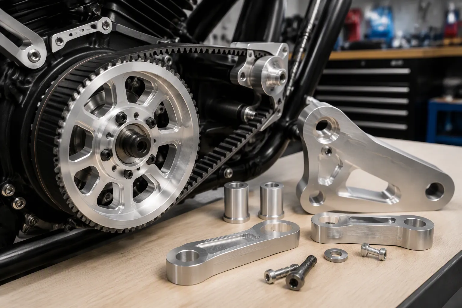
When you’re building mechanical equipment or modifying motorcycles for the US market, every component must deliver strength, precision, and reliability. That’s why custom 7075-T6 aluminum CNC machined parts have become the go-to choice for engineers and builders who demand performance without compromise. Compared to 6061-T6, 7075-T6 offers nearly double the strength:
- 7075-T6: ultimate tensile strength 572 MPa; yield strength 503 MPa; fatigue endurance 10⁷ cycles at 200 MPa
- 6061-T6: tensile strength 310 MPa; yield strength 276 MPa; fatigue endurance 10⁶ cycles at 150 MPa
- Both alloys share a density of approximately 2.7–2.8 g/cm³, giving you lightweight design flexibility
In high-stress applications like motorcycle belt pulleys, passing inspection at the fitting stage is only the beginning. The real test is holding tight tolerances under torque, vibration, heat, and anodizing processes. The right combination of alloy selection, machining strategy, finish specifications, and RFQ clarity directly influences both cost and performance. Qingdao Xuxiangtai supplies custom 7075-T6 aluminum CNC machined parts specifically for US mechanical equipment and motorcycle modification buyers—engineered to be manufacturable, repeatable, and precisely spec’d so you get exactly what you need without paying for unnecessary extras.
Key Takeaways
- Select 7075-T6 aluminum for high-stress motorcycle pulleys. It offers double the 6061-T6 strength. This keeps parts strong without extra weight.
- Use stress-relieved T651 aluminum for thin-wall pulleys. Machine both sides with balanced passes. This prevents warping. Tight tolerances remain.
- Send a complete RFQ package with CAD, 2D drawing, material temper. Include finish inspection needs. This yields accurate quotes. Quality parts follow.
Best-Fit Applications for Custom 7075-T6 Aluminum CNC Machined Parts
Motorcycle Belt Pulleys and Drivetrain Components
Motorcycle belt pulleys demand exceptional strength-to-weight ratios. You need parts that resist torque, vibration, and heat without adding unnecessary mass. 7075-T6 aluminum delivers tensile strength of approximately 510–540 MPa and yield strength of 430–480 MPa. These properties let your pulleys handle intense drivetrain loads while resisting permanent deformation. The material also provides excellent fatigue resistance under cyclic loading, which suits the repeated stress cycles your motorcycle experiences.
High-Load Mechanical Equipment Parts
Several industries rely on 7075-T6 for demanding applications:
- Aerospace frames and structural components
- Bicycle frames
- Tooling and precision fixtures
- Gears and shafts
- Structural marine and automotive parts
- Plastic injection molds
Motorsport applications include suspension components, steering knuckles, and driveline housings. These parts must withstand dynamic loads, impact forces, and thermal distortion. Aerospace brackets and wing fixtures require dimensional stability across temperature variations. Defense and industrial equipment use rugged housings and structural inserts that resist high stress and deformation.
US Mechanical Equipment & Motorcycle Modification Buyers
American buyers in mechanical equipment and motorcycle modification markets prioritize performance and reliability. You want parts that meet tight tolerances and hold up under real-world conditions. Qingdao Xuxiangtai supplies custom 7075-T6 aluminum CNC machined parts specifically for these buyers. The company understands your need for repeatable quality and manufacturable designs.
When 6061-T6 Is the Better Choice
7075-T6 is not always the right answer. Consider 6061-T6 when your application requires:
| Criterion | 6061-T6 Advantage |
|---|---|
| Corrosion resistance | Superior natural protection in humid or marine environments |
| Weldability | Good with TIG/MIG methods; 7075-T6 is generally unsuitable |
| Formability | Better for bending and complex shapes |
| Raw material cost | Lower due to higher production volumes |
"Choose 6061 for general-purpose machined components, 7075 for maximum strength, and 2024 for fatigue-critical parts exposed to repeated loading."
Send your CAD drawings and specifications to Qingdao Xuxiangtai for a detailed quotation and technical consultation.
Machining Route and Design Rules for 7075-T6
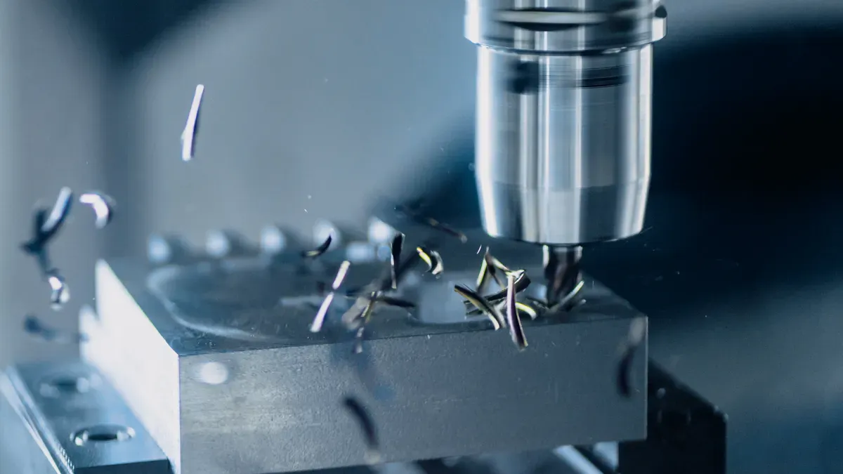
You have selected 7075-T6 for its strength and weight advantages. Now you need a machining strategy that preserves those properties through every operation. The alloy’s high yield strength resists deformation during cutting, but this same property increases tool stress and wear. A disciplined approach to tooling, fixturing, and process sequencing separates parts that hold tolerance from those that drift after unclamping.
CNC Milling, Turning, and Fixturing Considerations
Your tooling choices directly affect surface finish, dimensional accuracy, and cycle time. Carbide tooling is the industry standard for production work on 7075-T6. Carbide holds sharp edges at high speeds, resists heat buildup, and allows aggressive feeds without rapid wear. High-speed steel works only for low-volume jobs and limits your spindle speed and feed rates.
End mill selection depends on your operation. Use 2-flute end mills for maximum chip clearance and smooth cuts. Choose 3-flute cutters for a better balance of strength and speed on deeper passes. High-helix tools pull chips upward and prevent chip packing in the cut. For drilling, use carbide-tipped or solid carbide drills with a 130–140 degree point angle and polished flutes. Maximize rigidity with the shortest flute length and largest shank diameter your feature allows.
Speeds and feeds follow a simple principle: run high spindle speeds with consistent feed pressure. This produces thick, well-formed chips that carry heat away from the cutting edge. Slow feeds cause rubbing rather than cutting, which generates heat and accelerates wear. Use a strong air blast or flood coolant to clear chips before they are recut. Chip re-cutting destroys surface finish and accelerates tool wear.
Fixturing demands equal attention. Excessive clamping force distorts the workpiece, and the part may spring back to a shifted shape once you release the clamp. Soft jaws or full-face support distribute clamping loads evenly and minimize localized deformation. For thin plates, step clamping or vacuum fixtures prevent localized distortion. Because 7075-T6 has high yield strength, it resists deformation during cutting and in-service loading, which helps maintain dimensional retention. This also raises tool stress and wear, so sharp carbide tools with controlled engagement are preferred.
For turning operations, maintain concentricity by using live tooling to handle cross-drilling, flats, and off-axis features in a single setup. Re-fixturing a soft workpiece makes concentricity harder to hold than on steel. For high-precision turning tighter than ±0.002 inch, control tool engagement, cutting speed, and coolant temperature to manage thermal expansion. Aluminum moves roughly twice as much as steel per degree of temperature change, so shop temperature and coolant management directly affect dimensional accuracy. Swiss machining eliminates deflection that small-diameter aluminum parts are prone to during turning, allowing tolerances to ±0.001 inch.
Tolerances, GD&T, and Stress-Relieved Stock
Tolerance specification requires balance. For many non-critical machined dimensions, a supplier may work with a general shop tolerance near ±0.10 mm or ±0.005 inch unless your drawing says otherwise. That is not a universal aluminum standard or a guaranteed capability for every feature. A tolerance such as ±0.005 mm may be possible on a selected, accessible feature under controlled conditions. You should not treat it as a standard capability for every dimension on an aluminum part.
| Feature | Recommended Value | Feasible Limit | Rationale |
|---|---|---|---|
| Minimum wall thickness | ~1.0 mm | ~0.6–0.7 mm for short sections | Thicker walls improve rigidity and reduce chatter, deflection, and warping |
| Pocket depth | ~3× pocket width | Up to ~8–10× cutter diameter | Deep cavities require long tools that flex, reducing accuracy |
| Internal fillets | Radius ≥ 25–35% of cavity depth | Larger radii improve tool life | Larger radii accommodate tool geometry and reduce breakage risk |
| Tall features | Height-to-width ≤ 3.5:1 | Up to ~5:1 with careful fixturing | Slender features vibrate and lose tolerance |
| Standard tolerances | ±0.10 mm | Down to ±0.02–0.03 mm | Tight tolerances should be applied only where necessary to control cost and inspection time |
| Surface roughness | Ra ~3.0 µm as-machined | Ra ~0.4–0.8 µm after finishing | Default surfaces show cutter marks; finishing improves roughness |
Your GD&T callouts should include primary, secondary, and tertiary datums, controlled hole patterns, basic dimensions, position tolerance, material condition modifiers where appropriate, inspection basis, and final machined or finished condition. These elements give your supplier a complete picture of functional requirements.
Material condition matters as much as alloy selection. Aluminum plate may contain residual stress from rolling, heat treatment, straightening, and stretching. Uneven material removal changes the stress balance, causing bowing, twisting, or opening after unclamping. Stress-relieved 7075-T651 stock reduces this risk. The T651 designation indicates the plate was mechanically stretched by roughly 1.5%–3% before artificial aging, which evens out through-thickness stress and improves dimensional stability during machining. Mechanical properties remain essentially identical between T6 and T651, so the choice is driven by machining stability and flatness rather than strength.
| Characteristic | 7075-T6 | 7075-T651 (stress-relieved) |
|---|---|---|
| Residual stress level | Higher | Lower (stress relieved) |
| Post-machining warping | More likely | Minimal |
| Flatness tolerance | Standard | Better |
| Typical use case | General structure, non-critical brackets | Precision parts, aerospace, tooling plates |
Residual stress distortion occurs when one face of a stressed billet is machined first, releasing locked-in compressive forces and warping the part unpredictably. For thin-walled parts or flatness-critical fixtures, specify stress-relieved stock or use a symmetric material removal sequence that balances forces on both faces before taking finishing passes.
For small, relatively rigid parts, the difference between T6 and T651 may not create a noticeable machining issue. For large plates, thin-wall parts, or components with deep pockets and heavy material removal, T651 is often preferred because distortion control becomes more important. When sourcing material for precision CNC machining, checking the temper is as important as checking the alloy.
Preventing Distortion in Thin-Walled Pulleys
Motorcycle belt pulleys often feature thin walls, deep pockets, and tall features that challenge dimensional stability. You can prevent distortion through careful process design and fixturing strategy.
Start with stress-relieved tempers such as 7075-T651. Apply symmetrical roughing: remove roughly half the pocket volume from one side, flip the part, machine the other side, then perform thermal conditioning before final finishing passes. Perform inter-stage thermal stress relief by baking the partially machined component at about 175°C for 4 hours, then cooling slowly in a furnace to relax work hardening before final sizing. Use vacuum fixtures or low-clamping-force chucks for finishing instead of rigid mechanical clamps to avoid introducing clamping stresses into the thin-walled geometry.
Al7075-T651 holds thin-wall features down to about 0.50 mm. A minimum wall thickness of about 0.8 mm is recommended for CNC aluminum parts to maintain rigidity and reduce vibration or warping. Geometry optimization should limit thin-wall ratios, match internal radii to cutter sizes, and sequence rough-to-finish passes to keep features stable. Distortion control should machine in stages, leave uniform stock for finishing, and alternate machining sides to balance internal stress release. Fixturing should use stable datum surfaces, in-process probing, and controlled tool overhang to reduce vibration and maintain tolerances.
Distortion in 7075 aluminum is driven by residual stress from quenching and is influenced by pocket depth, wall geometry, and removal sequence. Even stress-relieved T651 plate is not immune to movement. Balanced stock removal, stable workholding, rough-and-rest cycles, intermediate inspection, and sufficient finish allowance are recommended for critical walls and bores. For thin walls, alternate sides or operations where practical, and allow thermal stabilization before final measurement. Document grain direction and part orientation when directional properties matter.
| Factor | Effect on Distortion | Recommended Planning Action |
|---|---|---|
| Asymmetric pockets / thin walls / deep removal | Identified as distortion risks before stock selection | Review these features early; plan roughing, support, and inspection around potential movement |
| Thin unsupported walls, abrupt section changes, deep cavities, long narrow arms | Increase importance of sequencing and support | Define functional datums; flag surfaces needing a final pass after reclamping |
| Bulk material removal | Distortion risk when removal is uneven | Separate bulk removal from final sizing; rough in a balanced pattern leaving finish allowance; allow blank to relax, reorient, or remeasure |
| Clamping of flexible parts | Can force a part into apparent correctness, masking free-state distortion | Specify whether critical features are measured free-state, in a defined support condition, or in an assembly-like fixture |
| Inspection setup | Can be as consequential as material callout for distortion-sensitive parts | Agree measurement setup, support points, temperature conditions, and datum-restraint scheme |
Choosing a more stable material condition can lower machining risk, but it cannot compensate for an unbalanced machining sequence or poor fixture design.
The correct finishing allowance depends on part size, alloy and material condition, wall thickness, required flatness, tolerance, material-removal ratio, and fixture rigidity. Allow parts to stabilize at room temperature before inspection. A part that measures correctly at the spindle can grow measurably by the time it reaches the inspection table.
How Qingdao Xuxiangtai Approaches 7075-T6 Machining
Qingdao Xuxiangtai applies a structured process sequence to every custom 7075-T6 aluminum CNC machined part. The approach begins with stock selection. For heavily pocketed plate parts, stock condition and stress relief matter more than lowest raw-material price. The team checks stock flatness, surface condition, extra material for workholding, grain direction, material lot consistency, and certification requirements before machining begins.
The process sequence follows a proven path:
- Select appropriate stock and verify material certification
- Choose the correct temper based on dimensional stability requirements
- Account for residual stress through rough machining followed by stress relief before finishing
- Control machining-induced stress through tool sharpness, cutting force, temperature, toolpath, and coolant delivery
- Manage clamping distortion with uniform distributed clamping and low-contact workholding
- Define the inspection state before machining begins
- Apply thin-wall machining strategies that sequence stress relief, roughing, finishing, and inspection
Tool selection follows the same disciplined approach. The team uses sharp carbide end mills with 2 or 3 flutes, high helix angles around 38–45 degrees, and polished flutes. ZrN coating or uncoated polished carbide minimizes aluminum adhesion. Flood water-soluble coolant manages heat, washes away chips, and prevents re-cutting. Where flood is not feasible, a powerful air blast with mist lubricant provides adequate cooling and chip evacuation.
For drilling and tapping, the team uses pecking cycles for depths beyond 3x diameter, dwells at the bottom of each peck to break chips, and reduces feed as the drill exits through-holes. Spiral-point taps handle through-holes, and spiral-flute taps handle blind holes. Thread milling is available for critical threads.
Finishing passes use light depths of cut of 0.005–0.015 inch with high spindle speed and moderate feed. Climb milling is preferred. Tool runout is minimized. For near-mirror finish, a sharp finishing end mill with adjusted SFM and feed per tooth delivers the required surface quality. Deburring removes stubborn burrs manually with scrapers or files, or through thermal energy methods for production quantities.
The company also accounts for anodizing dimensional growth, typically 0.0005–0.002 inch per surface for Type III hardcoat. Precision bores are masked or post-machined to preserve fit. Post-machining heat treatment on finished 7075 parts is avoided because quenching causes warping. When heat treatment is necessary, rough-machined blanks are heat treated then finish machined.
This systematic approach produces custom 7075-T6 aluminum CNC machined parts that hold tolerance under torque, vibration, heat, and anodizing. The goal is a manufacturable, repeatable part without unnecessary specifications that drive cost.
Send your CAD file, 2D drawing with GD&T, material and finish specifications, and target quantity to Qingdao Xuxiangtai for an accurate quote and technical consultation. The team provides design-for-manufacturing feedback before production begins, helping you optimize features for machining efficiency and dimensional stability.
Finishes, Risk Controls, and RFQ Inputs for Custom 7075-T6 Parts
You have selected the alloy, planned the machining route, and controlled distortion during cutting. The next decisions determine whether your part survives real service conditions. Finish selection, corrosion protection, and RFQ completeness all influence final performance and cost. Each choice carries trade-offs you need to understand before you commit to production.
Anodizing and Hardcoat Behavior on 7075-T6
Anodizing dominates surface treatment for 7075-T6 parts. The process grows an aluminum oxide layer from the base metal. This layer provides corrosion protection, wear resistance, and color options. Two main types serve different purposes.
Type II anodizing produces a thinner coating of 5–25 µm with surface hardness around 200–400 HV. You get full dye range and moderate wear resistance. Type III hardcoat builds a thicker layer of 25–100 µm with hardness reaching 600–700 HV. This coating delivers extreme abrasion resistance for sliding surfaces and high-wear zones.
| Finish Type | Thickness | Surface Hardness | Corrosion Resistance (ASTM B117) | Key Characteristics |
|---|---|---|---|---|
| Type II Anodizing | 5-25 µm | 200-400 HV | 336+ Hours | Decorative, accepts dyes, moderate wear resistance |
| Type III Hardcoat | 25-100 µm | 600-700 HV | 1000-2000+ Hours | Extreme abrasion resistance, alters dimensions |
| MIL-DTL-5541 (Chem Film) | <1 µm | N/A | 168-336 Hours | Maintains electrical conductivity, excellent paint base |
| Electroless Nickel | 12.7-38.1 µm | Up to 800 HK100 | High | Uniform deposit, high lubricity, requires heat treatment |
Dimensional change demands your attention. A coating grows about half its thickness outward from the original surface. A diameter moves by roughly the full coating thickness, and a bore loses it. Type III hardcoat at 50 µm per surface adds approximately 0.002 inch to an outer diameter and removes the same from a bore. You must pre-compensate in your CAD model or mask critical features before anodizing.
Fatigue life presents another consideration. MIL-PRF-8625 states that anodic coatings can severely reduce fatigue properties of aluminum alloys. The oxide layer is hard and brittle. Under cyclic load, it cracks before the aluminum does. Each crack introduces a stress riser at the surface where fatigue cracks initiate. Thicker coatings cause greater reduction. Fatigue-critical structural drawings often call for Type I or Type IB, confine Type III to a defined wear zone, or prohibit hardcoat entirely.
7075-T6: High strength. Anodizes darker. Hardcoat works well but color matching is harder.
Color variation is normal for 7075-T6. The alloy composition produces brown or golden tones instead of bright silver. You should accept this as a material characteristic and communicate expectations to your finishing supplier.
Corrosion, Stress Cracking, and Tolerance Stack-Up Risks
7075-T6 contains zinc, magnesium, and copper. These elements deliver high strength but create corrosion vulnerabilities. Machining removes the natural oxide layer and leaves fresh surfaces chemically active. Residual cutting fluid, improper cleaning, or humid storage can cause dark spots and corrosion before surface finishing begins.
Material handling controls prevent these problems. Verify alloy grade upon receipt. Keep surfaces clean and avoid contamination. Control storage conditions with low humidity and stable temperature. Use suitable cutting parameters during machining and control coolant concentration. Clean parts immediately after machining, remove coolant residue, dry parts properly, and protect them before anodizing.
Anodizing itself carries process risks you should understand.
| Anodizing Risk | Root Cause | Control Measure |
|---|---|---|
| Coating flaking / loss of adhesion | Hydrated aluminum oxide has a different coefficient of expansion than 7075; zinc migrates to grain boundaries during heat treating; work hardening from dull tools, tumbling, or blasting | Avoid steel shot peening (imbeds iron particles); control heat treatment; avoid work-hardened surfaces before anodizing |
| Blisters in hard coat | Trapped hydrogen from alloy manufacture; inadequate surface prep (sanding, bead blasting imbed non-anodizable matter); incomplete deoxidizing | Proper cleaning and deoxidizing; avoid mechanical abuse during surface prep; careful control of dye/prep steps |
| Cracking at high temperature | Large thermal expansion difference between aluminum alloy and aluminum oxide; thicker coatings more susceptible | Limit service temperature; consider thinner anodic coatings |
| Color variation (brown/golden instead of silver) | Normal material characteristic of 7075 due to alloy composition | Accept as material characteristic; communicate expectations |
Stress corrosion cracking presents the most serious risk for 7075-T6 in chloride environments. SCC requires three simultaneous conditions: a susceptible alloy microstructure, a corrosive environment, and sustained tensile stress. The T6 temper is the most SCC-prone among 7xxx alloys, especially in the short-transverse direction. Chloride exposure can reduce fatigue life by 40–60%.
| Alloy & Temper | IGC Susceptibility | SCC Susceptibility | Recommended Mitigation | Typical Application |
|---|---|---|---|---|
| 7075-T6 | Moderate | Very High | Use T73 temper for critical applications | Aircraft structures (legacy) |
| 7075-T73 | Low | Low | Preferred temper for SCC-prone environments | Modern aircraft, oil & gas |
| 7050-T7451 | Low | Very Low | Best SCC-resistant 7xxx alloy for thick sections | Aircraft wing spars, bulkheads |
The T73 and T76 over-aged tempers were developed to improve SCC resistance dramatically. These tempers sacrifice 10–15% strength compared to T6. For motorcycle belt pulleys and mechanical equipment parts exposed to road salt or marine environments, you should evaluate whether T73 temper or enhanced coating protection makes sense for your application.
Galvanic corrosion occurs when 7075-T6 contacts dissimilar metals in the presence of moisture. The galvanic series determines which metal corrodes. Aluminum sits near the active end, so it becomes the anode and corrodes preferentially when coupled with most other metals.
| Metal in Contact with Aluminum | Galvanic Risk Level | Required Protection | Acceptable in Dry Indoor? | Acceptable Outdoors? |
|---|---|---|---|---|
| Magnesium | Benign (Mg is anodic to Al) | Mg corrodes instead; acceptable with Mg coating | Yes | With caution |
| Zinc / Galvanized Steel | Low (Zn is anodic) | Zn coating eventually consumed; monitor | Yes | Yes, if Zn coating maintained |
| Cadmium-Plated Steel | Low | Minimal (Cd is close to Al in series) | Yes | Yes |
| Carbon Steel | Moderate-High | Insulating washers, coating, or sealing required | Marginally | No—isolate |
| Stainless Steel (304, 316) | High | Mandatory isolation: nylon washers, sealant, coating | With isolation | No—always isolate |
| Copper / Brass / Bronze | Very High | Never direct contact in wet environments; severe pitting risk | Avoid | Never |
| Graphite / Carbon Fiber | Very High | Fiberglass isolation layer, sealant, cathodic protection | Avoid | Never without isolation |
You can reduce galvanic risk through several design choices. Use insulating gaskets made from nylon, PTFE, or neoprene between dissimilar metals. Apply wet-install sealant such as polysulfide or polyurethane. Specify cadmium-plated or zinc-coated fasteners. Apply protective coatings to both metals. Never rely on paint alone for galvanic protection because pinholes in the coating create a highly unfavorable area ratio that accelerates pitting.
Tolerance stack-up compounds these risks. Anodizing changes dimensions. Thermal expansion moves features during operation. Assembly forces can shift components. You must account for all these factors when you specify tolerances on your drawing.
Aluminum expands at 23.6 µm/m-°C. A 200 mm pulley experiencing a 40°C temperature rise grows by approximately 0.19 mm. This movement can exceed your tolerance band if you do not plan for it. Temperature-controlled environments during machining, typically maintained at 20°C with chilled coolant systems and real-time thermal compensation, help hold sub-0.01 mm tolerances during production. Your design must account for thermal movement in service.
Precision tolerances for custom 7075-T6 aluminum CNC machined parts typically fall into these ranges:
- Standard tolerances: ±0.002″ to ±0.005″
- Tight tolerances: ±0.0004″ to ±0.001″
- Ultra-precision: down to ±0.0001″ under strictly controlled conditions
First Pass Yield benchmarks help you evaluate supplier capability. World-class FPY for precision CNC machining exceeds 95%. The industry average runs 84–88%. The bottom quartile falls below 80%. Improving FPY by 1% can reduce the cost of poor quality by 3–5%. Single-source manufacturing consolidates milling, finishing, and inspection under one roof. This approach eliminates vendor handoffs, maintains traceability, and ensures consistent quality from prototype to production.
What to Include in Your RFQ Package
A complete RFQ package prevents quote revisions, production delays, and quality disputes. You should include specific documents and information that give your supplier everything needed to quote accurately and manufacture correctly.
Start with your 3D CAD model. STEP AP214 or AP203 format works best for geometry transfer. Verify the model is at the current revision level. The model defines complex surfaces and features that drawings cannot easily describe.
Add a 2D drawing in PDF format. The drawing carries dimensions, tolerances, threads, GD&T callouts, surface finish symbols, material specification, heat treatment, and plating or coating requirements. The drawing revision must match the 3D model revision. State which document governs in case of conflict.
Your drawing should include these elements:
- Primary, secondary, and tertiary datums
- Controlled hole patterns with position tolerance
- Basic dimensions and material condition modifiers where appropriate
- Surface roughness requirements (Ra values) for functional surfaces
- Thread specifications with class of fit
- Inspection basis and final machined or finished condition
Material specification requires precision. Write 7075-T6 or 7075-T651 instead of "aluminum." The temper designation matters for machinability, dimensional stability, and corrosion resistance. Include applicable material standards and certification requirements such as material certificates, lot traceability, or CoC.
Surface finishing specifications should cover anodizing type, color, coating thickness, surface roughness, appearance standards, and areas requiring masking or protection. If you need Type III hardcoat on specific wear surfaces only, mark those areas clearly. If you need masked threads or bores, note them on the drawing.
Quantity and delivery conditions complete your package. List sample and production quantities separately. State your target lead time, packaging requirements, shipping destination, and whether you expect repeat orders. Include your Estimated Annual Usage so your supplier can optimize pricing for your real production scale.
| RFQ Omission | How It Causes Inaccurate Quotes / Production Issues |
|---|---|
| Missing critical tolerances | Suppliers interpret acceptable variation differently (e.g., ±0.1 mm vs ±0.02 mm), producing wildly different quotes for the same part; tolerance gaps also affect machining strategy, tool selection, inspection, cycle time, and scrap risk. |
| No annual volume estimates | Suppliers must guess production scale; prototype vs. 5,000 pcs/year changes fixture investment, tooling strategy, and inspection planning, so quotes may not match the buyer’s real long-term plan. |
| Vague material specification | Descriptions like "aluminum" or "stainless steel" omit grade; 6061-T6 vs 7075-T6 differ in mechanical properties, corrosion resistance, machinability, and cost, so suppliers may quote the most expensive option to "play it safe." |
| Unclear surface finish requirements | Anodizing, bead blasting, powder coating, electropolishing, passivation, or roughness specs (e.g., Ra 1.6 μm) significantly affect machining time and inspection, forcing quote revisions and delays when omitted. |
| Undefined quality documentation | Buyers assume material certs, dimensional inspection reports, or FAI are included, but suppliers may only provide basic shipping docs unless requirements (COC, CMM, PPAP, calibration records) are stated at RFQ stage. |
Common omissions cause predictable problems. Sending only a STEP file without a 2D drawing omits tolerances, surface roughness, and thread specifications. The machinist defaults to standard tolerances, which often leads to assembly failure. Missing tolerances force shops to default to ±0.1 mm or ±0.2 mm. A press-fit bearing requirement then yields a 100% rejection rate during assembly.
Over-constrained tolerances drive up costs exponentially. Blanket ±0.01 mm tolerances across a drawing increase machining and inspection costs even though critical features typically represent only 10–20% of the drawing. Apply tight tolerances only where function requires them.
Drawing and model mismatches stop production. When 2D dimensions conflict with 3D geometry, suppliers must request clarification. This wastes time and makes quotes impossible to compare horizontally. Keep all documents at the same revision and state units clearly.
Secondary operations and inspection requirements raised after quoting invalidate the original price. State anodizing, plating, heat treatment, FAI, material certificates, and CMM inspection requirements at the RFQ stage. Your quote will then reflect the true cost of your quality level.
A complete RFQ package for custom 7075-T6 aluminum CNC machined parts includes:
- 3D CAD model in STEP format at current revision
- 2D drawing in PDF with full dimensioning, tolerances, and GD&T
- Material specification with alloy and temper designation
- Surface finish requirements with Ra values and coating specifications
- Quantity per part number for samples and production
- Delivery destination and target lead time
- Inspection and documentation requirements
- Precedence note stating whether drawing or model governs
Send your CAD file, 2D drawing with GD&T, material and finish specifications, and target quantity to Qingdao Xuxiangtai for an accurate quote and technical consultation. The team provides design-for-manufacturing feedback before production begins. This partnership approach helps you optimize features for machining efficiency, dimensional stability, and finish performance. You receive a manufacturable, repeatable part without paying for unnecessary specifications.
Choose 7075-T6 when your application demands high strength, low weight, and tight tolerances. Manufacturability, finish selection, and RFQ completeness decide final performance. Send your CAD file, 2D drawing with GD&T, material and finish specs, and target quantity to Qingdao Xuxiangtai. You receive an accurate quote and design-for-manufacturing feedback before production begins.
FAQ
When should you choose 7075-T6 over 6061-T6 for motorcycle pulleys?
Choose 7075-T6 when your pulley faces high torque, vibration, and cyclic loads. It delivers nearly double the strength of 6061-T6. Select 6061-T6 for marine exposure or welded assemblies instead.
What tolerances can you expect on custom 7075-T6 aluminum CNC machined parts?
Standard tolerances run ±0.002" to ±0.005". Tight tolerances reach ±0.0004" to ±0.001". Ultra-precision hits ±0.0001" under controlled conditions. Specify tight tolerances only on functional features to control cost.
How does anodizing affect 7075-T6 pulley dimensions?
Anodizing grows the oxide layer outward and inward. Type III hardcoat at 50 µm adds roughly 0.002" to an outer diameter. You must pre-compensate in your CAD model or mask critical bores before finishing.
What should you include in your RFQ for 7075-T6 parts?
Send a 3D CAD model in STEP format, a 2D drawing with GD&T, material and temper specs, finish requirements, and target quantities. Include inspection needs and delivery destination. This package prevents quote revisions and production delays.
Ready to move your project forward? Send your CAD file, 2D drawing with GD&T, material and finish specifications, and target quantity to Qingdao Xuxiangtai. You receive an accurate quote and design-for-manufacturing feedback before production begins.
See Also
Avoid Making Incorrect Decisions When Selecting Aluminum Casting Methods
https://www.xuxiangtaimetal.com/
Qingdao Xuxiangtai Machinery
