
For beverage plant engineers and liquid packaging line investors, selecting the high-pressure air compressor is one of the most critical engineering decisions in a PET bottle stretch blow molding project. Across production rates between 2,000 and 12,000 bottles per hour (BPH), compressed air demand scales rapidly. An improperly matched compressor does not simply increase operating electricity draw; it creates line throttling, destabilizes container wall thickness, and triggers unplanned downtime across downstream filling operations.
Zhangjiagang Grandee Machinery Co., Ltd., manufacturing under the brand name Grandee Machine, engineers complete liquid bottling plants across capacities from 2,000 to 36,000 BPH. In production plant design, compressed air supply is not a secondary utility; it is the pneumatic backbone determining whether blowing and filling lines sustain rated speeds.
This technical guide examines the pneumatic sizing variables, thermodynamic energy drivers, and line integration configurations across the 2,000 to 12,000 BPH capacity window.
Two-Stage Compressed Air Mechanics in PET Stretch Blow Molding
PET bottle blow molding relies on two distinct pneumatic pressure stages synchronized with mechanical stretch rods:
- Pre-Blow Phase (Low-to-Medium Pressure, 0.6–1.0 MPa / 6–10 bar): As the stretch rod extends the preform axially to the base of the mold cavity, low-pressure air expands the preform radially. This stage controls longitudinal material distribution and prevents the preform wall from chilling prematurely against the mold steel.
- Final High-Pressure Blow Phase (High Pressure, 2.5–3.5 MPa / 25–35 bar, up to 4.0 MPa for CSD bottles): Once the preform reaches full stretch, high-pressure air forces the PET resin against the chilled mold walls. This pressure establishes container definition, forms petaloid or flat base ribs, and transfers heat into the mold cooling channels.
The high-pressure stage represents the dominant electricity consumer on the production floor. Because compression power scales with mass flow and pressure ratio, sizing the compressor requires calculating continuous volume consumption while buffering peak instantaneous demand.
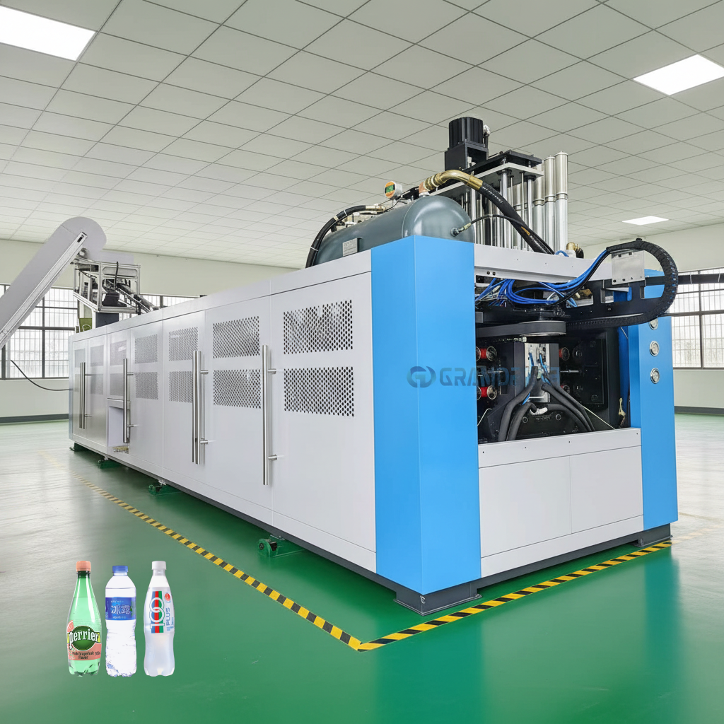
Engineering Sizing Matrix: 2,000 to 12,000 BPH Bottling Lines
The table below provides typical high-pressure air compressor matching parameters for standard 500 ml PET bottled water production:
| Blowing Line Capacity (500 ml Basis) | Typical Mold Cavity Configuration | Required High-Pressure Air Volume (FAD at 3.0 MPa) | Recommended Compressor Motor Power (Indicative) | Air Receiver Storage Volume (Minimum Buffer) |
|---|---|---|---|---|
| 2,000–3,000 BPH | 2-Cavity Linear / Rotary | 1.8–2.5 m³/min (65–90 CFM) | 22–30 kW | 1.0 m³ at 3.0 MPa |
| 4,000–6,000 BPH | 4-Cavity Linear / Rotary | 3.5–5.2 m³/min (125–185 CFM) | 45–55 kW | 1.5–2.0 m³ at 3.0 MPa |
| 8,000–9,000 BPH | 6-Cavity Rotary | 7.0–8.2 m³/min (250–290 CFM) | 75–90 kW | 2.5–3.0 m³ at 3.0 MPa |
| 10,000–12,000 BPH | 8-Cavity Rotary | 9.0–11.5 m³/min (320–410 CFM) | 90–110 kW | 3.0–4.0 m³ at 3.0 MPa |
Core Sizing Variables Across the 2,000–12,000 BPH Range
- Instantaneous Peak Flow vs. Average Free Air Delivery (FAD): High-pressure blowing occurs during a brief fraction of the machine cycle (typically 0.4 to 0.8 seconds per bottle). A compressor sized solely for average hourly consumption will experience pressure sag during simultaneous blow valve openings. Installing properly sized high-pressure air receivers directly adjacent to the blow molder dampens pressure oscillation and protects container quality.
- Piping Distribution Pressure Drop: Long runs of small-bore piping between the compressor room and the blowing hall induce significant friction losses. A pressure drop of 0.3 MPa (3 bar) along supply headers forces the compressor to generate 3.3 MPa to deliver 3.0 MPa at the blow nozzle, directly increasing electrical draw. Ring-main piping designs with smooth-radius stainless steel bends keep distribution losses below 0.05 MPa.
- Air Quality and Moisture Management: Wet or oil-contaminated air damages high-speed pneumatic valves and compromises container food safety. High-pressure air systems must incorporate refrigerated air dryers maintaining a pressure dew point of 2°C to 5°C (or desiccant dryers reaching −40°C in tropical high-humidity climates), paired with coalescing particulate and oil-removal filters rated to 0.01 micron.
Energy Management and Operational Levers
High-pressure air compressors represent one of the primary electricity consumers in a beverage plant. Plant managers can implement several mechanical and operational measures to control energy draw:
- Precise Pressure Set-Point Tuning: Operating the blow molder at the lowest pressure that achieves complete container base and thread definition minimizes excess energy consumption. Every 0.1 MPa (1 bar) reduction in compressor discharge pressure reduces compressor motor power demand by approximately 6% to 8%.
- Air Recovery Systems (Exhaust Recycling): Advanced blow molding carousels incorporate air recovery valves that capture high-pressure exhaust air after the final blow phase. This recycled air is redirected into the low-pressure pre-blow loop or plant utility headers, recovering up to 30% to 40% of compressed air volume.
- Variable Speed Drive (VSD) Integration: In plants operating multi-format schedules or running at partial capacity during line changeovers, VSD compressors modulate motor RPM to match real-time consumption, eliminating the energy waste associated with unloaded idling cycles.
System Architecture: Separated Lines vs. Rotary Monoblock Systems
A fundamental engineering choice governing compressed air demand is the mechanical interface between the blow molder and the filling carousel:
In conventional separated configurations (typical for 2,000 to 10,000 BPH lines), bottles discharge from the blow molder and travel to the filler via stainless steel air conveyors. Centrifugal air blowers continuously inject low-pressure air along conveyor tracks to propel bottles by their neck rings. This introduces an auxiliary electrical load and creates potential airborne particulate contamination.
In integrated rotary blow-fill-cap monoblock systems (engineered for high-speed lines from 12,000 to 36,000 BPH), blowing, filling, and capping are mechanically synchronized on a single continuous transfer carousel. Bottles are handed directly from blow molds to filling valves via precision starwheels:
- Elimination of Air Conveyors: Mechanical starwheel transfer eliminates pneumatic conveying tracks entirely, removing conveyor blower power consumption and saving up to 10% compressed air consumption across the line.
- Thermal and Floor Footprint Efficiency: Eliminating buffer air conveyors shortens the footprint by 15 to 25 meters, while bottles enter filling valves immediately after blowing without losing residual heat. In-house test data demonstrates up to 30% electrical energy savings across integrated monoblock platforms relative to conventional separated lines.
For operations within the 2,000 to 12,000 BPH range, Grandee Machine integrates high-efficiency standalone blow molders with its 3-in-1 rotary water filling machines (covering 2,000 to 32,000 BPH on a 500 ml basis). These systems incorporate 316L stainless steel liquid contact parts, precision electronic volumetric filling valves, and positive-pressure HEPA laminar flow enclosures for purified and mineral water lines.
Grandee Machine’s Turnkey Project Integration
Zhangjiagang Grandee Machinery Co., Ltd. delivers complete liquid packaging plants under a turnkey project delivery model. This engineering scope integrates high-pressure compressor matching, 3D paperless factory layout, equipment manufacturing, installation, commissioning, and operator training under a unified project schedule.
During the factory layout stage, Grandee Machine’s project engineers determine the optimal physical placement of the compressor room, sizing utility headers and condensate drainage lines to minimize pressure drop and thermal loading. To prevent contractual ambiguity, infrastructure boundaries are defined strictly: Civil works, building construction, floor trench drainage excavation, civil cleanroom paneling, and primary plant utility connections (main electrical substation transformers, municipal water intake piping, compressed air plant headers, and external boiler steam piping) are excluded from the turnkey project scope.
Frequently Asked Questions
A: Standard flat-base or lightweight PET water bottles typically require 2.5 to 3.0 MPa (25–30 bar) final blowing pressure. In contrast, carbonated soft drink bottles featuring thick petaloid bases require 3.2 to 3.8 MPa (32–38 bar) to force the rigid resin into sharp base contours that resist internal carbonation pressure.
A: No. High-pressure air compressors must be housed in a dedicated, well-ventilated utility room isolated from sanitary filling zones. Compressors generate acoustic noise (75–85 dBA) and substantial rejected heat. Isolating them protects food hygiene standards and allows maintenance technicians to service air filters without entering cleanroom enclosures.
A: A 6,000 BPH line consuming approximately 4.5 m³/min of high-pressure air requires a minimum storage buffer of 1.5 to 2.0 m³ rated at 3.0 MPa. The receiver dampens cyclic pressure pulsing from reciprocating compressor pistons and supplies instantaneous air during simultaneous cavity blow cycles.
A: White haze typically results from either preform overheating (causing thermal crystallization of the PET resin) or insufficient blowing pressure that fails to stretch the material fully before it chills. Excessive moisture in the high-pressure air supply can also disrupt cooling, emphasizing the need for verified air dryer performance.
A: Daily checks include verifying automatic condensate drain operation and inspecting oil levels. Routine intake air filter replacement occurs every 1,000 to 2,000 hours, lubricating oil and oil filter changeover at 2,000 to 4,000 hours, and comprehensive valve and piston ring overhaul every 8,000 operational hours.
About Grandee Machine
Zhangjiagang Grandee Machinery Co., Ltd. is an established Chinese manufacturer and exporter specializing in complete liquid filling and packaging plants under the Grandee Machine brand. Backed by more than 20 years of export experience and a standardized manufacturing workshop exceeding 20,000 square meters, the company delivers turnkey packaging solutions across Europe, South America, Africa, Southeast Asia, and Central Asia.
Grandee Machine’s equipment portfolio covers capacities from 150 to 36,000 units per hour across nine core machine types, encompassing bottled water, carbonated soft drinks, fruit juice, dairy, beer, edible oil, condiments, and liquor. Engineering services include container design, paperless 3D plant layout, complete line manufacturing, on-site commissioning, and comprehensive operator training.
Next Step
To receive a tailored equipment and high-pressure compressor matching schedule for your bottling line, prepare your production parameters:
- Container specifications: Bottle drawing or sample with target neck finish, height, diameter, and weight.
- Target production output in bottles per hour (BPH) across standard formats (e.g., 500 ml and 1,500 ml).
- Electrical supply characteristics (voltage, frequency, and transformer capacity).
- Ambient environmental conditions (temperature and relative humidity range at the plant site).
Submit your site data to Grandee Machine’s engineering team to receive complete 2D footprint layouts, pneumatic flow diagrams, and equipment integration proposals.
Related Reading
https://www.grandeemachine.com/
Zhangjiagang Grandee Machinery Co., Ltd.
