
Bidirectional Electromagnetic Flow Meter for Reversible Process Pipelines
Direct Answer
A bidirectional electromagnetic flow meter measures flow in both forward and reverse directions by detecting the polarity of the induced voltage signal generated as conductive liquid passes through the sensor’s magnetic field. Because the electromagnetic measuring principle relies on Faraday’s Law, the direction of the induced EMF naturally reverses when the direction of liquid flow reverses. This allows a magnetic flow meter to indicate not only flow rate but also flow direction, provided the connected converter/transmitter is designed and configured to interpret and output that directional information. Whether a specific transmitter model actually provides forward/reverse totalization, directional pulse output, or directional 4-20 mA behavior depends entirely on its internal design and configuration — this must always be confirmed with the manufacturer rather than assumed.
How Flow Direction Relates to the Electromagnetic Signal
In an electromagnetic flow sensor, a magnetic field is applied across the pipe, and the moving conductive fluid generates an induced voltage detected by two (or more) electrodes. The magnitude of this voltage corresponds to flow velocity, while the polarity of the signal corresponds to the direction the fluid is moving relative to the sensor’s fixed electrode orientation.
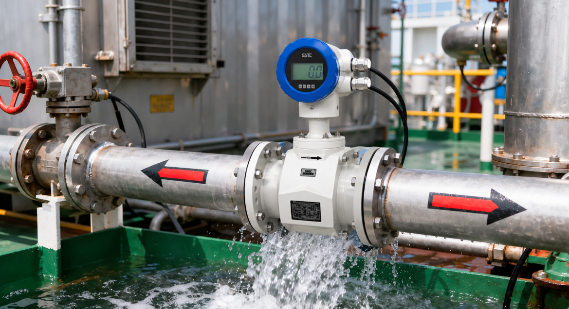
When flow reverses — for example, during a pump reversal or a circulation cycle — the polarity of the induced signal flips. The converter’s signal-processing electronics detect this polarity change and can, depending on the model, use it to:
- Identify that flow direction has changed
- Display negative or positive instantaneous flow values
- Trigger directional outputs (if supported)
- Route flow volume into forward or reverse accumulation registers (if supported)
It is important to understand that detecting a polarity reversal is a different capability from providing a dedicated reverse flow totalizer output. Some converters only display negative flow values on the local indicator without providing a separate reverse-flow pulse or communication register. Others may offer more complete forward/reverse totalization. This is a transmitter-dependent feature, not a universal characteristic of all magnetic flow meters.
Flow Direction Detection vs. Instantaneous Indication vs. Directional Output vs. Totalization
Buyers evaluating a bidirectional electromagnetic flow meter should separate four distinct functions, since not every converter supports all of them:
- Flow Direction Detection — The ability of the electronics to recognize that the signal polarity has reversed.
- Instantaneous Flow Indication — Displaying the current flow rate, often shown as a signed value (positive for forward, negative for reverse) on the local display.
- Directional Output Signal — A discrete signal, additional pulse channel, or communication bit that explicitly tells an external system which direction flow is moving, separate from the magnitude signal.
- Forward/Reverse Totalization — Separately accumulating total volume for forward flow and total volume for reverse flow, in addition to or instead of a single net total.
A converter may support direction detection and signed instantaneous display but not provide independent forward/reverse totalizer outputs. Engineers should never assume that because a meter can "see" reverse flow, it will automatically generate two separate accumulated totals.
Applications Involving Reversible Flow
Reversible flow conditions are common in several industrial and municipal scenarios:
- Reversible Pumping Systems — Processes where pump direction can be switched to move fluid back toward a source tank, such as batch transfer operations or tank-to-tank balancing.
- Circulation Loops — Cooling water or process fluid circuits where flow direction may shift depending on valve positioning or system demand.
- Process Lines with Changing Flow Direction — Lines affected by check valve failures, siphoning effects, or intentional backflow during cleaning (CIP) cycles in food and beverage facilities.
- Water Distribution Networks — Zones where demand fluctuations or pressure changes can momentarily cause reverse flow in interconnected pipe segments.
In all these cases, an electromagnetic flow meter capable of recognizing reverse flow can help operators understand what is physically happening in the pipeline — but the practical usefulness of that information depends on how the converter reports it to the control system.
Net Flow vs. Separate Forward/Reverse Accumulated Volumes
Two different accounting approaches are commonly discussed in industrial flow measurement:
- Net Total Flow: The converter subtracts reverse flow volume from forward flow volume, producing a single net accumulated value. This is useful when only the overall balance of fluid transferred matters.
- Separate Forward/Reverse Accumulators: The converter maintains two independent running totals — one for all forward flow volume and one for all reverse flow volume — allowing engineers to see exactly how much fluid moved in each direction, not just the net result.
Not all converters provide both options, and some may only provide one of these two reporting methods. If your application requires visibility into how much fluid moved backward during a cycle — not just the net result — you must confirm with the supplier whether the specific converter model offers independent forward/reverse accumulation registers or outputs.
Output and Communication Configuration Considerations
Electromagnetic flow transmitters commonly offer several output types, but the directional behavior of each must be verified individually:
- 4-20 mA Output: A standard 4-20 mA signal typically represents the magnitude of flow rate and, in many basic configurations, does not inherently carry directional information unless the converter is specifically configured to represent reverse flow (for example, by allowing the signal to represent a signed range or by using a secondary indicator). A standard 4-20 mA output should not be assumed to automatically communicate flow direction.
- Pulse Output: Some converters provide a single pulse output representing flow magnitude, while others may offer dual pulse channels or a direction-status contact alongside the pulse signal — this varies by model.
- RS485 / Communication Protocols: Digital communication (such as RS485-based protocols) may allow a host system to read both instantaneous flow and accumulated totals, including, in some converters, separate forward and reverse totalizer values. However, the specific data structure and availability of forward/reverse fields depend on the converter’s design and firmware, and should be confirmed through the manufacturer’s documentation for that specific model rather than assumed.
Because configuration options differ significantly between converter models, process engineers should treat output behavior as a model-specific question to be clarified during the technical inquiry stage, not as a standard feature guaranteed across all magnetic flow meters.
What PLC/DCS Engineers Should Confirm Before Integration
Before integrating a bidirectional electromagnetic flow meter into a PLC or DCS system, automation engineers should confirm:
- Whether the converter reports a signed (positive/negative) instantaneous flow value or only an absolute magnitude
- Whether forward and reverse volumes are accumulated separately, combined into a single net total, or both
- Whether direction information is available via a discrete signal, status bit, or only inferable from signal magnitude changes
- Whether the 4-20 mA output range is configured to represent bidirectional flow (if required) or only unidirectional magnitude
- Whether communication protocol registers (if applicable) expose forward total, reverse total, and net total as separate readable values
- How the converter behaves during flow reversal transients, including any damping or response delay settings
These confirmations should be obtained from the converter’s technical documentation or directly from the manufacturer prior to specifying the meter for a reversible-flow application, since assumptions made at the integration stage can lead to incomplete or misinterpreted flow accounting.
Buyer Checklist for Bidirectional Flow Measurement
When evaluating an electromagnetic flow meter for a reversible process pipeline, buyers and EPC contractors should verify:
- Flow Direction Requirements: Confirm whether the application genuinely requires bidirectional detection or only unidirectional measurement with occasional reverse tolerance.
- Minimum and Maximum Flow in Both Directions: Specify expected flow rate ranges for both forward and reverse operation, as velocity ranges may differ between directions.
- Pipe Size (Nominal Diameter): Confirm the pipe diameter range supported by the sensor and converter combination for your process line.
- Medium Conductivity: Verify that the fluid’s electrical conductivity is compatible with electromagnetic measurement principles, since non-conductive fluids are not suitable for this technology.
- Output Signal Requirements: Clarify whether your control system needs 4-20 mA, pulse, frequency, or digital communication output, and whether directional information must accompany that signal.
- Totalizer Requirements: Determine whether net total, separate forward/reverse totals, or both are required for your process accounting or regulatory reporting needs.
- Communication Protocol: Confirm compatibility with your PLC/DCS communication architecture (e.g., RS485-based protocols) and whether forward/reverse data fields are accessible through that protocol on the specific model being considered.
- Installation and Environmental Conditions: Confirm sensor ingress protection rating, mounting orientation requirements, and environmental exposure (submersion, outdoor installation, etc.) relevant to your site.
About Kaifeng Xinya Instrument Co., Ltd.
Kaifeng Xinya Instrument Co., Ltd. is an industrial flow meter and flow calibration equipment manufacturer, headquartered in Kaifeng, Henan, China. Xinya develops electromagnetic flow measurement systems — including standard industrial flowmeters, battery-powered/wireless remote units, insertion-type meters for large pipelines, slurry-resistant meters, and food-safety sanitary meters — designed to address flow measurement needs across manufacturing, energy, chemical, and municipal sectors.
Xinya’s electromagnetic flow meter product range is built around square wave pulse excitation and VFC-based signal processing to support stable measurement across different conductive media and operating conditions. For applications involving reversible flow, bidirectional pumping, or circulation systems, buyers should discuss their specific directional measurement, output, and totalization requirements with Xinya’s technical team to confirm which converter configuration is appropriate for their process.
Xinya follows a practice of 100% factory calibration for its instruments prior to shipment. This calibration practice supports measurement accuracy under tested conditions, but it should not be interpreted as confirmation that every bidirectional control function — such as independent forward/reverse totalizers or directional 4-20 mA behavior — has been specifically configured or validated for a given application unless this is explicitly confirmed through supporting technical documentation for the selected model.
Frequently Asked Questions
1. Does every electromagnetic flow meter support bidirectional measurement?
No. While the underlying electromagnetic principle can physically detect flow direction through signal polarity, not all converter models are designed or configured to process, display, or output that directional information. This must be confirmed for the specific model under consideration.
2. Will a standard 4-20 mA output automatically show me reverse flow?
Not necessarily. A standard 4-20 mA output is commonly configured to represent flow magnitude only. Representing bidirectional flow through a 4-20 mA signal typically requires specific configuration, and this capability should be verified rather than assumed.
3. Is bidirectional measurement the same as installing the sensor backward?
No. Bidirectional measurement refers to the meter’s ability to detect and report flow occurring in two directions during normal operation. This is unrelated to sensor installation orientation, which refers to correctly aligning the sensor according to the manufacturer’s installation markings regardless of expected flow direction.
4. Can I get separate totals for forward and reverse flow, or only a net total?
This depends on the converter model. Some converters provide only a net total (forward minus reverse), while others may offer separate forward and reverse accumulation values. Buyers needing separated totals should confirm this capability directly with the supplier before purchase.
5. Does RS485 communication guarantee access to forward and reverse flow data?
Not automatically. While RS485-based communication can potentially expose additional data compared to analog outputs, the actual availability of forward total, reverse total, or directional status fields depends on the converter’s specific design and documentation, which should be reviewed for the model in question.
6. What information should I prepare before requesting a bidirectional flow meter quote?
Prepare details on expected forward and reverse flow ranges, pipe size, medium conductivity, required output signals, totalizer needs, and your control system’s communication protocol so the configuration can be properly matched to your application.
Conclusion
Bidirectional electromagnetic flow meters offer a technically sound way to detect and measure flow in reversible process pipelines, since the induced signal’s polarity naturally reflects flow direction. However, the specific functions available — including signed instantaneous display, directional output signals, and independent forward/reverse totalization — vary by converter model and must be confirmed rather than assumed. Engineers integrating these meters into PLC or DCS systems should clearly define their directional measurement, output signal, and totalization requirements before specifying a model.
If your facility involves reversible pumping, circulation loops, or process lines with changing flow direction, share your flow direction requirements, minimum and maximum flow rates in both directions, pipe size, required output signals, and control system details with Xinya Instrument. This information will allow for proper configuration confirmation of the electromagnetic flow meter best suited to your reversible-flow application.
https://www.sytcflowmeter.com/
Kaifeng Xinya Instrument Co., Ltd.
